Liquid crystal panel, driving method thereof, and liquid crystal display device containing the same

Inactive Publication Date: 2014-01-16
INNOLUX CORP
View PDF6 Cites 10 Cited by
  • Summary
  • Abstract
  • Description
  • Claims
  • Application Information

AI Technical Summary

Benefits of technology

[0010]An object of the present invention is to provide a liquid crystal panel and a liquid crystal display device c

Problems solved by technology

In addition, the conventional backlight is unpolarized light, so a polarizer has to be disposed on a side of the TFT substrate to change the unpolarized backlight into polarized light before the backlight propagates into the liquid

Method used


Image

  • Liquid crystal panel, driving method thereof, and liquid crystal display device containing the same
  • Liquid crystal panel, driving method thereof, and liquid crystal display device containing the same
  • Liquid crystal panel, driving method thereof, and liquid crystal display device containing the same

Examples


Example

Embodiment 1

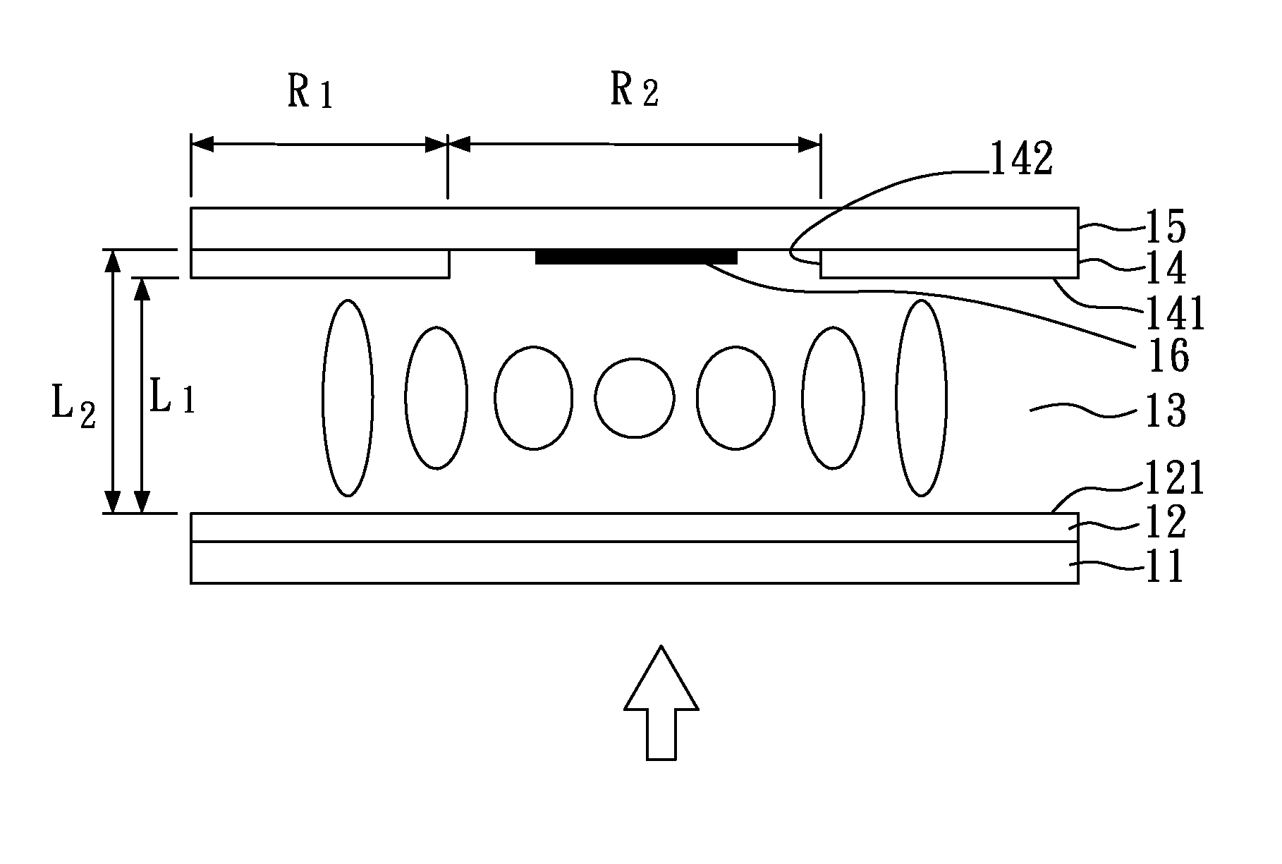
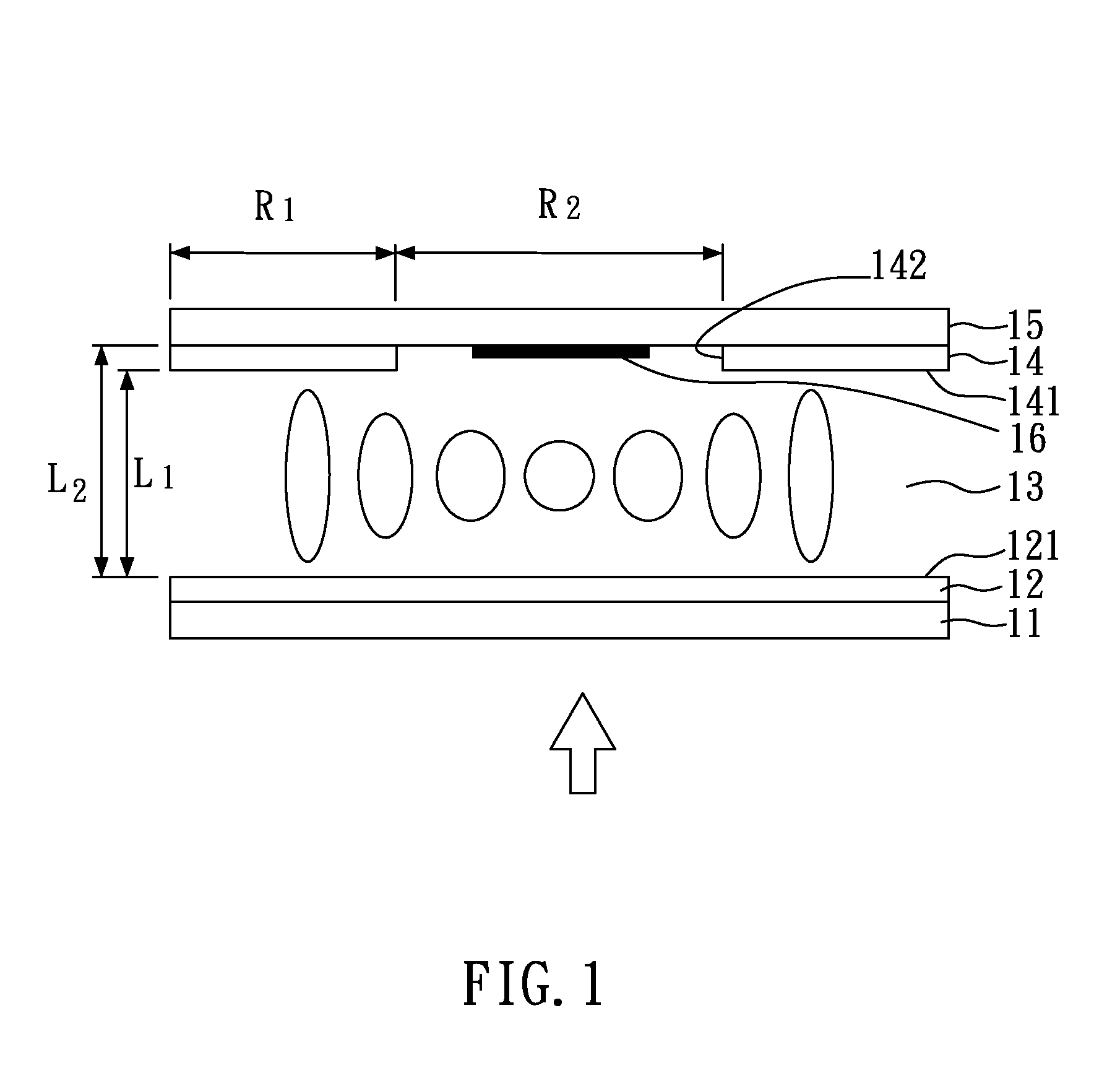
[0036]FIG. 1 is a cross-sectional view showing a liquid crystal panel of the present embodiment after a bias voltage is provided thereto, and FIG. 2 is a perspective view showing the liquid crystal panel of the present embodiment before a bias voltage is provided thereto.

[0037]As shown in FIG. 1 and FIG. 2, the liquid crystal panel of the present embodiment comprises: a first substrate 11 having a first electrode layer 12, wherein the first electrode layer 12 has a first surface 121; a second substrate 15 having a second electrode layer 14 opposite and parallel to the first electrode layer 12, the second electrode layer 14 has a second surface 141, and the second surface 141 faces to the first surface 121 of the first electrode layer 12; a blue-phase liquid crystal layer 13 comprising blue-phase liquid crystals and disposed between the first substrate 11 and the second substrate 15; and a light-shielding region 16 disposed on a surface of the second substrate 15 facin...

Example

Embodiment 2

[0042]FIG. 3 is a perspective view showing a liquid crystal panel of the present embodiment before a bias voltage is provided thereto. As shown in FIG. 3, the structure of the liquid crystal panel and the method for driving the same of the present embodiment are similar to those of Embodiment 1, except that a micro-lens array 17 is disposed under the second electrode layer 14 and faces to the first electrode layer 12. The disposed micro-lens array 17 can facilitate the light, which passes through the blue-phase liquid crystal layer 13, focusing on the light-shielding region 16. In other embodiments, the micro-lens array may be disposed between the second electrode layer 14 and the second substrate 15, if it is necessary.

Example

Embodiment 3

[0043]FIG. 4 is a cross-sectional view showing a liquid crystal panel of the present embodiment after a bias voltage is provided thereto. As shown in FIG. 4, the structure of the liquid crystal panel and the method for driving the same of the present embodiment are similar to those of Embodiment 1, except that a dielectric layer 19 is disposed under the second electrode layer 14 and faces to the first electrode layer 12. The disposed dielectric layer 19 can facilitate the light, which passes through the blue-phase liquid crystal layer 13, focusing on a light-shielding region (not shown in the figure). In addition, the liquid crystal panel of the present embodiment does not comprise the light-shielding region of Embodiment 1. In the present embodiment, the incident light passing through the blue-phase liquid crystal layer 13 is designed to focus on a black matrix of a color filter 18, in which the black matrix can absorb the focusing light.


PUM


Abstract

A liquid crystal panel, a driving method thereof, and a liquid crystal display device containing the same are disclosed. The liquid crystal panel of the present invention comprises: a first substrate having a first electrode layer; a second substrate having a second electrode layer opposite to the first electrode layer; a blue-phase liquid crystal layer disposed between the first substrate and the second substrate; and a light-shielding region disposed on the second substrate. When a bias voltage is applied to the first electrode layer and the second electrode layer, a refractive gradient is formed in the blue-phase liquid crystal layer, and thereby an incident light passing through the blue-phase liquid crystal layer focuses on the light-shielding region.

Description

CROSS REFERENCE TO RELATED APPLICATION[0001]This application claims the benefits of the Taiwan Patent Application Serial Number 101124763, filed on Jul. 10, 2012, the subject matter of which is incorporated herein by reference.BACKGROUND OF THE INVENTION[0002]1. Field of the Invention[0003]The disclosure relates to a liquid crystal panel, a driving method thereof, and a liquid crystal display device containing the same and, more particularly, to a liquid crystal panel using a blue-phase liquid crystal layer as a gradient refractive index lens, a driving method thereof, and a liquid crystal display device containing the same.[0004]2. Description of Related Art[0005]A liquid crystal display (LCD) is a flat panel display with a thin thickness, so a conventional cathode ray tube (CRT) display is gradually replaced by the LCD. Nowadays, the LCD becomes one of the most popular displays.[0006]The LCD mainly comprises a liquid display panel and a backlight module disposed under the liquid d...

Claims


Application Information

Patent Timeline
IPC IPC(8): G02F1/133
CPCG02F1/13306G02F1/133509G02F1/134309G02F1/13793
Inventor YANG, KEI-HSIUNGWENG, RUEY-JER
Owner INNOLUX CORP
Why Eureka
Try Eureka