Method of controlling pitch systems of a wind turbine

Inactive Publication Date: 2014-01-16
SIEMENS AG
View PDF3 Cites 12 Cited by
  • Summary
  • Abstract
  • Description
  • Claims
  • Application Information

AI Technical Summary

Benefits of technology

[0029]The frequency with which a pitch system should be actuated may depend not only on the various performance parameters mentioned above, but also on the current situation inside the bearing itself. For example, even though lubricant can be topped up at regular intervals by a lubricant system, the level of lubricant in a pitch bearing may drop slightly over time, and this may well have a detrimental effect on the performance of the bearing. The viscosity of the lubricant can also alter over time or according to the temperature inside the pitch bearing. Therefore, in a particularly preferred embodiment of the invention, the system comprises

Problems solved by technology

It is of paramount importance that the lubricant is evenly distributed in the pitch bearing, since a jamming or locking of the bearing could cause serious damage to the wind turbine.
However, for low wind speeds, or at higher constant wind speeds, the wind turbine controller may only infrequently carry out very minor adjustments to the pitch angle, or no adjustments at all, so that the collective pitch angle remains essentially constant, and the pitch systems remain essentially inactive over long periods of time.
As a result, the lubricant in a pitch bearing may be unsatisfactorily distributed, and damage to the pitch bearing, the actuator, or even the wind turbine itself may ensue if the bearing becomes blocked or jammed In a kn

Method used


Image

  • Method of controlling pitch systems of a wind turbine
  • Method of controlling pitch systems of a wind turbine
  • Method of controlling pitch systems of a wind turbine

Examples


first embodiment

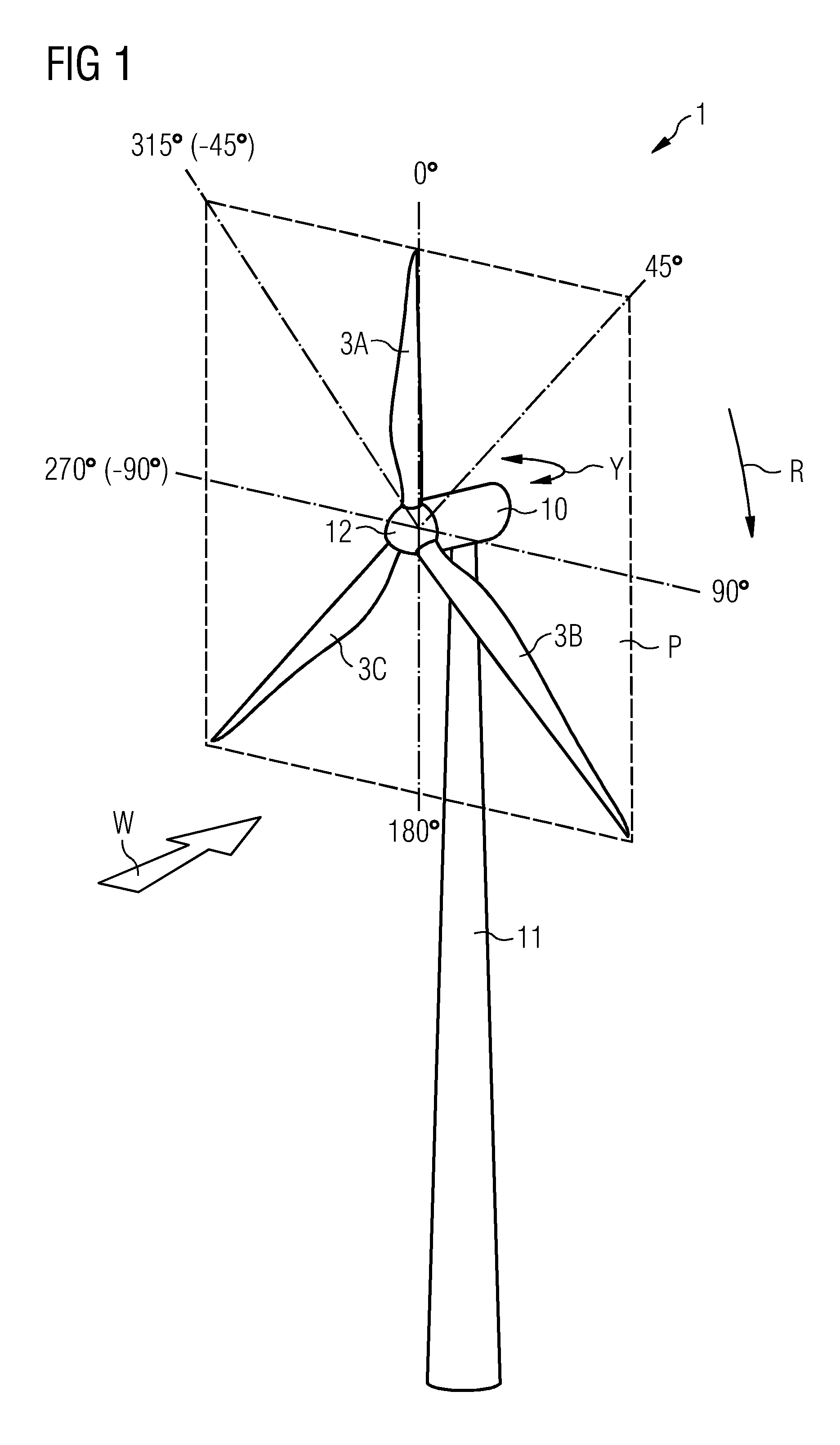
[0047]FIG. 5 shows a graphical representation of a plurality of auxiliary pitch control signals 4A, 4B, 4C generated using the method according to the invention. The auxiliary pitch control signals 4A, 4B, 4C are applied to the respective rotor blades at certain defined intervals. Here, an auxiliary pitch control signal 4A, 4B, 4C is applied to its rotor blade when the rotor blade passes through the sector within ±90° about the reference 0° as described in FIG. 1. The circle described by a blade over time as it rotates from 0° to 360° is visually presented here by the sawtooth graphs 5A, 5B, 5C of blade angular travel. For the sake of simplicity, it is assumed that the blades rotate with a constant rotational velocity, with correspondingly uniform sawtooth graphs. Considering a first blade with sawtooth graph 5A: the auxiliary pitch control signal 4A for that blade is applied from the time the blade passes the 270° position until it passes through the 90° position of the rotational ...

second embodiment

[0049]FIG. 6 shows a graphical representation of a plurality of auxiliary pitch control signals 4A, 4B, 4C generated using the method according to the invention. Here, the time interval between successive auxiliary pitch control signals 4A, 4B, 4C is smaller. As the first blade 3A passes through the upper half of the rotational plane P shown in FIG. 1, i.e. through the sector given by ±90° about the reference 0°, its auxiliary pitch control signal 4A is applied. As the next blade 3B enters this sector, the first blade 3A still has 60° of travel to complete in the upper half of the rotational plane. Therefore, the auxiliary pitch control signals 4A, 4B overlap over a certain time interval, and the same applies for the auxiliary pitch control signals 4B, 4C. Here, only one set of three auxiliary pitch control signals 4A, 4B, 4C is shown. Of course, an auxiliary pitch control signal 4A, 4B, 4C could be applied to each blade during each rotation, so that the auxiliary pitch control sign...

third embodiment

[0050]FIG. 7 shows a graphical representation of a plurality of auxiliary pitch control signals 4A, 4B, 4C generated using the method according to the invention. As shown in FIG. 6 above, the auxiliary pitch control signals 4A, 4B, 4C are applied successively during one rotation of the hub. Here, however, an auxiliary pitch control signal 4A, 4B, 4C is applied as a blade passes through the sector given by ±45° about the reference 0°, i.e. through a quarter of the rotational plane. Therefore, the auxiliary pitch control signals 4A, 4B do not overlap. Again, only one set of three auxiliary pitch control signals 4A, 4B, 4C is shown, but it is to be understood that this sequence of auxiliary pitch control signals 4A, 4B, 4C could be applied to the blades repeatedly, for example after a certain time has elapsed, after a certain number of revolutions of the hub, according to a pitch activity history, etc.

[0051]Although the present invention has been disclosed in the form of preferred embo...


PUM


Abstract

A method is provided for controlling the pitch systems of a plurality of pitch systems of a wind turbine. The method includes generating a main pitch control signal for the pitch systems on the basis of a performance parameter of the wind turbine and generating a distinct auxiliary pitch control signal for each individual pitch system of the plurality of pitch systems. The method further includes adding an auxiliary pitch control signal to the main pitch control signal to give a combined pitch control signal for a pitch system. The method then includes controlling that pitch system in response to that combined pitch control signal wherein an auxiliary pitch control signal is suppressed when a pitch activity value and/or a pitch variation value is below a predefined threshold.

Description

CROSS REFERENCE TO RELATED APPLICATIONS[0001]This application is the US National Stage of International Application No. PCT / EP2011 / 064134, filed Aug. 17, 2011 and claims the benefit thereof. The International Application claims the benefits of European application No. 11161524.1 EP filed Apr. 7, 2011. All of the applications are incorporated by reference herein in their entirety.FIELD OF INVENTION[0002]The invention describes a method of controlling the pitch systems of a wind turbine; a pitch control system for controlling the pitch systems of a wind turbine; and a wind turbine.BACKGROUND OF INVENTION[0003]A wind turbine generally comprises two or three rotor blades connected to a hub. Each blade is usually connected to the hub by means of a pitch system, whose function it is to allow the blade to rotate to some degree about its longitudinal axis in order to obtain an optimal pitch angle. To this end, a pitch actuator, for example an electrical motor, a hydraulic piston, or another...

Claims


Application Information

Patent Timeline
IPC IPC(8): F03D7/02
CPCF03D7/0224F03D7/024F03D7/043F05B2260/98F05B2270/326Y02E10/72
Inventor ESBENSEN, THOMASHOEGH, GUSTAV
Owner SIEMENS AG
Why Eureka
Try Eureka