Polymer scaffolds for peripheral vessels

a polymer scaffold and peripheral vessel technology, applied in the field of drugeluting medical devices, can solve the problems of most often occurring failure of the scaffold structure, and prior scaffold designs are most susceptible to crack formation, and achieve the effects of reducing the late lumen loss, discontinuity or percentage of fractured structures, and reducing late lumen loss

Active Publication Date: 2014-01-16
ABBOTT CARDIOVASCULAR
View PDF8 Cites 31 Cited by
  • Summary
  • Abstract
  • Description
  • Claims
  • Application Information

AI Technical Summary

Benefits of technology

[0017]In response to these needs there is provided a peripherally-implantable and bio-erodible polymer scaffold that has a lower fracture rate, discontinuity or percentage of fractured structure. The scaffold is capable of maintaining its scaffolding support of a vessel wall sufficiently for up to about a 1, 2, and 3 month period following implantation, following which the scaffolding begins to degrade as it should no longer be needed to maintain vascular patency. Surprisingly and unexpectedly, the polymer scaffold according to one embodiment is capable of producing a significantly lower late lumen loss than prior scaffold designs about 28 days after implantation.

Problems solved by technology

Tests have revealed that for a peripherally-implanted scaffold, particularly for scaffold located within arteries of appendages, failure in the scaffold structure has most often occurred due to repeated axial compression / extension and bending.
Although the scaffold is in general subjected to a complex and time-varying combination of radial, axial, bending and torsion loads, it has been found that prior scaffold designs have been mostly susceptible to crack formation due to repeated cyclic axial and bending loads, e.g., 500,000 cycles of 7% axial compression / extension, which is considered equivalent to walking over a six month period.

Method used


Image

  • Polymer scaffolds for peripheral vessels
  • Polymer scaffolds for peripheral vessels
  • Polymer scaffolds for peripheral vessels

Examples


Embodiment Construction

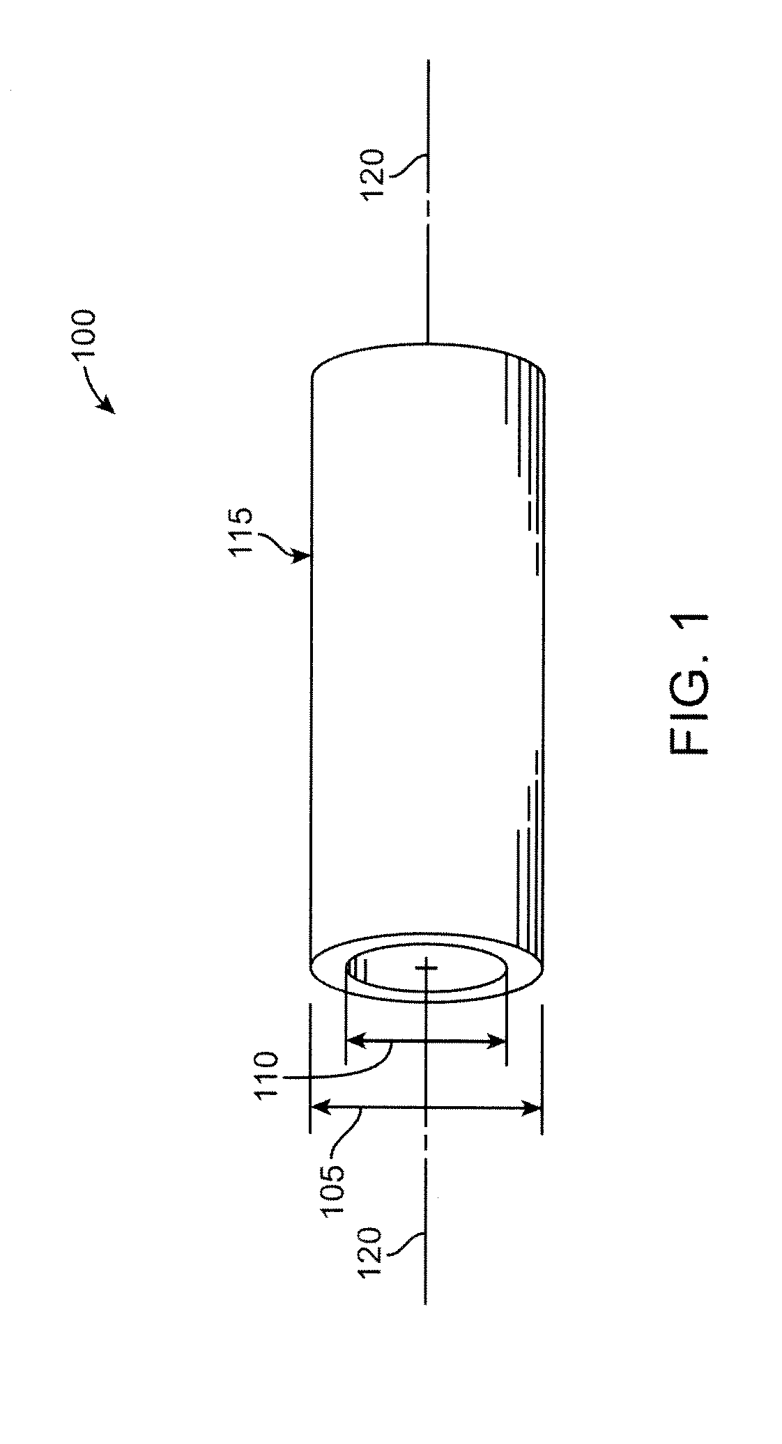
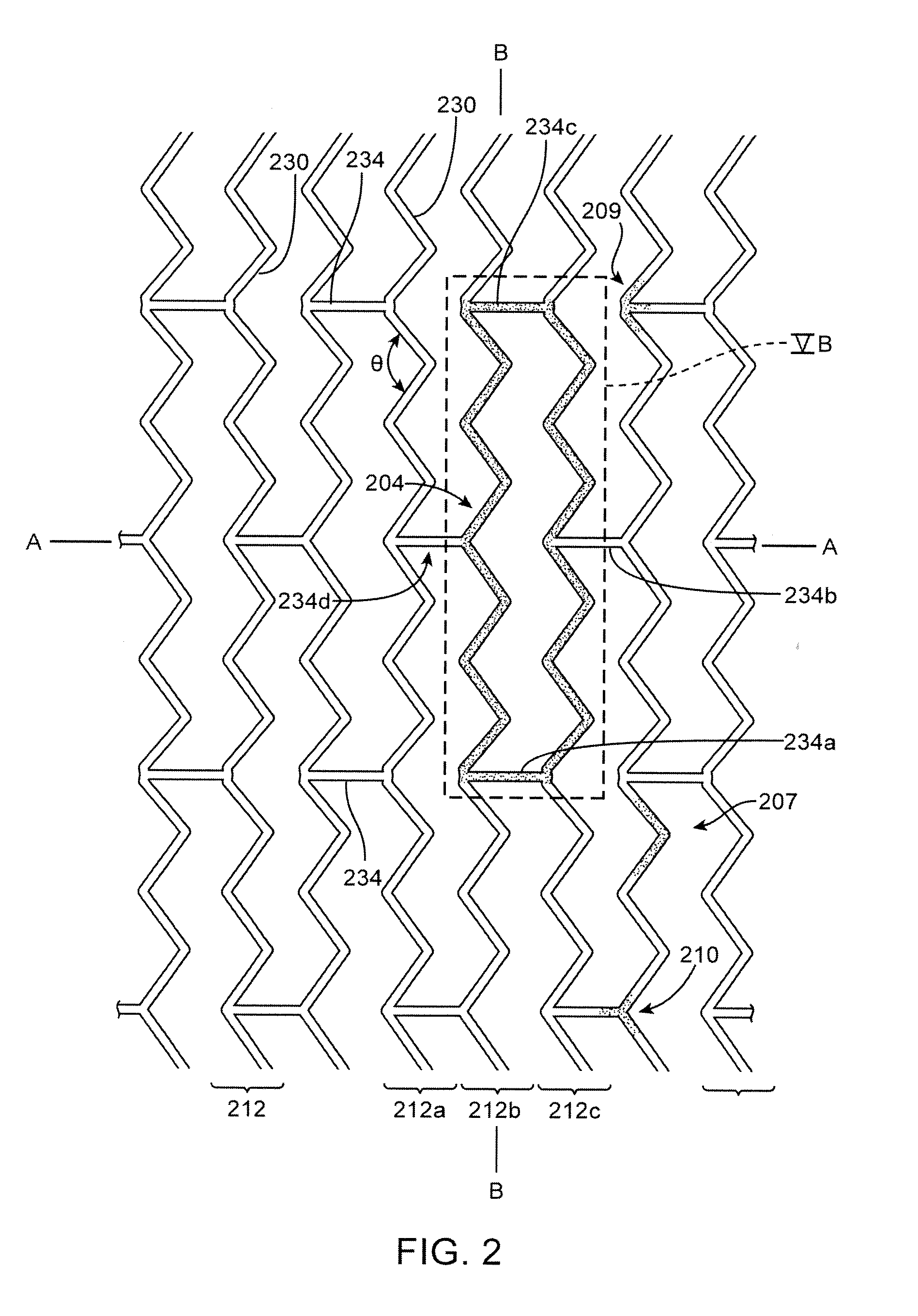
[0049]The disclosure proceeds as follows. First, definitions of terms that may be used during the course of the subsequent disclosure are explained. Embodiments of processes for forming a deformed polymer tube from a precursor are provided. According to the disclosure, the crush recoverable and balloon expandable scaffold is cut from a tube (FIG. 1) formed through a process intended to enhance mechanical properties of the scaffold including fracture toughness. Discussion of the scaffold patterns according to several embodiments are discussed next. Examples of the scaffold patterns are provided. During this discussion, reference is made to aspects of a scaffold found to play an important role in the stiffness, strength, crimping and deployment of a polymer scaffold. Finally, bench and in-vivo test results are discussed, including exemplary examples of embodiments of invention and explanation of the results observed and problems overcome. In these examples there may be gained a furthe...


PUM

PropertyMeasurementUnit
outer diameteraaaaaaaaaa
lengthaaaaaaaaaa

Abstract

A medical device includes a polymer scaffold crimped to a catheter having an expansion balloon. The scaffold has a structure that produces a low late lumen loss when implanted within a peripheral vessel and also exhibits a high axial fatigue life. In a preferred embodiment the scaffold forms ring structures interconnected by links, where a ring has 12 crowns and at most two links connecting adjacent rings.

Description

FIELD OF THE INVENTION[0001]The present invention relates to drug-eluting medical devices; more particularly, this invention relates to polymeric scaffolds that are expanded by a delivery balloon.BACKGROUND OF THE INVENTION[0002]Radially expandable endoprostheses are artificial devices adapted to be implanted in an anatomical lumen. An “anatomical lumen” refers to a cavity, duct, of a tubular organ such as a blood vessel, urinary tract, and bile duct. Stents are examples of endoprostheses that are generally cylindrical in shape and function to hold open and sometimes expand a segment of an anatomical lumen (one example of a stent is found in U.S. Pat. No. 6,066,167 to Lau et al). Stents are often used in the treatment of atherosclerotic stenosis in blood vessels. “Stenosis” refers to a narrowing or constriction of the diameter of a bodily passage or orifice. In such treatments, stents reinforce the walls of the blood vessel and prevent restenosis following angioplasty in the vascula...

Claims


Application Information

Patent Timeline
Patent Type & Authority Applications(United States)
IPC IPC(8): A61F2/82
CPCA61F2/915A61F2002/91575A61F2210/0004A61F2230/0054
Inventor ELI, ERIK DAVIDNGO, MICHAEL HUYTROLLSAS, MIKAELHOSSAINY, SYEDSMITH, JOSHUA TAKESHIDAVALIAN, DARIUSH
Owner ABBOTT CARDIOVASCULAR
Why Eureka
Try Eureka