Optical fiber lasers

a technology fiber optics, applied in the field of optical fiber lasers, can solve the problems of limited power levels of conventional solid-state lasers, general ineffectiveness, and limited cw power levels, and achieve efficient optical pumping, high intracavity power, and efficient nonlinear frequency conversion

Active Publication Date: 2014-01-23
UNIV OF SOUTHAMPTON
View PDF2 Cites 52 Cited by
  • Summary
  • Abstract
  • Description
  • Claims
  • Application Information

AI Technical Summary

Benefits of technology

[0058]Some embodiments employ a fiber laser configuration with an internal resonant enhancement cavity capable of yielding high intracavity power inside the enhancement cavity for efficient nonlinear frequency conversion and efficient optical pumping of weakly absorbing laser media and other mat

Problems solved by technology

Many applications require coherent laser emission in wavelength regimes (e.g. ultraviolet, visible and mid-infrared) that are not readily accessible by conventional diode-pumped solid-state lasers and fiber lasers.
Simple single-pass nonlinear frequency conversion in a suitable nonlinear crystal is a popular approach for high peak power pulsed laser sources, but is generally not very effective with lasers operating in continuous-wave (cw) mode as cw power levels are limited.
Unfortunately, power levels in conventional solid-state lasers are limited by thermal effects, which degrade efficiency and beam quality as pump power is increased.
Indeed, thermal effects can be especially detrimental to the performance of intracavity frequency-doubled solid-state lasers by virtue of the increased cavity loss associated with thermally-induced phase distortion.
As a consequence, this approach is generally limited to output power levels around a few tens-of-watts.
A further drawback of solid-state laser gain media is that the emission bands tend to be quite narrow limiting the range of operatin

Method used


Image

  • Optical fiber lasers
  • Optical fiber lasers
  • Optical fiber lasers

Examples


Embodiment Construction

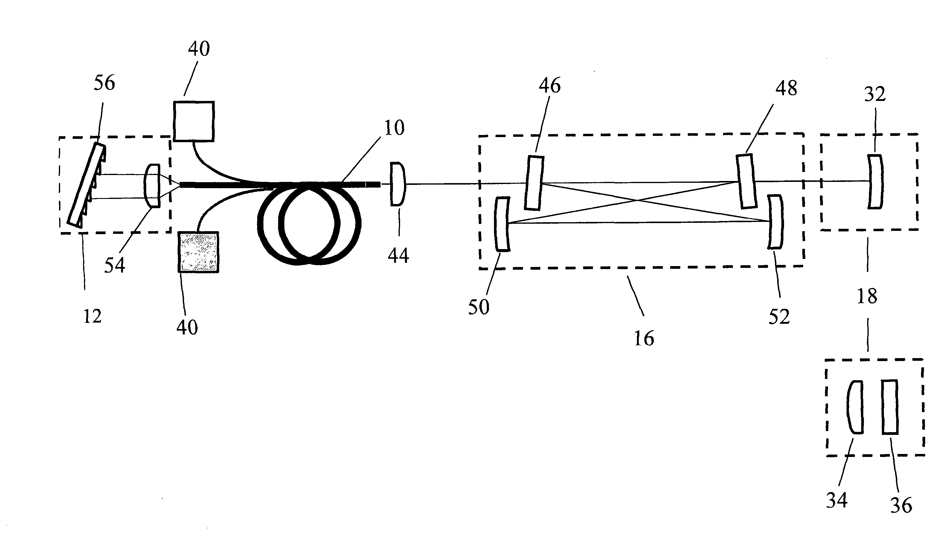
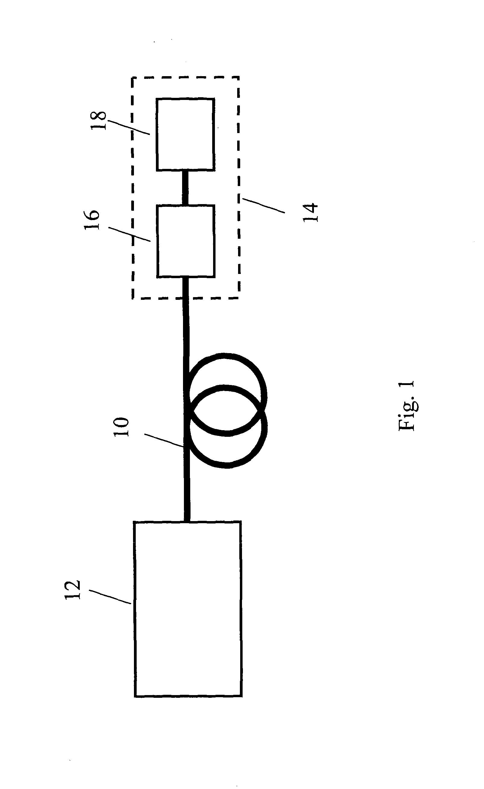
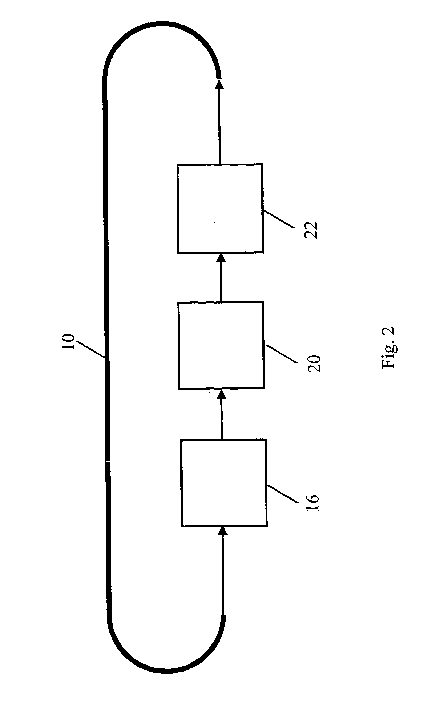
[0081]FIG. 1 is a schematic block diagram of an optical fiber laser device according to a first embodiment which is based on a linear or standing-wave resonator configuration. A portion of optical fiber 10 is provided having a core and a cladding. The core is doped with suitable rare earth ions or bismuth to provide gain. A standing-wave resonator cavity is formed around the fiber 10 by first and second reflectors 12 and 18. The first reflector 12 is wavelength selective. The second reflector 18 is a mirror. The mirror 18 is part of an external feedback cavity 14 also comprising a resonant enhancement cavity 16 arranged within the resonator cavity formed by the first and second reflectors 12 and 18.

[0082]The fiber laser source can operate on axial modes defined by the effective length of whole cavity 12, 18 that lie within the emission spectrum of the active ions and the range of operating wavelengths defined by the wavelength-selective reflector 12. The cavity length will also incl...


PUM


Abstract

A fiber gain medium provided by a rare-earth doped fiber (10) is contained in a first resonant cavity by end reflectors (12, 18). The reflector (12) is wavelength selective to limit the frequency band of the first resonant cavity. The first resonant cavity also contains a second resonant enhancement cavity (16) with multiple transmission bands lying within the first resonant cavity's frequency band. Multiple standing wave modes of the first resonant cavity lie within both the frequency band of the first resonant cavity and the transmission bands of the second resonant cavity, and it is these standing wave modes that support laser action when the rare-earth doped fiber is suitably pumped by pump lasers (40).

Description

BACKGROUND OF THE INVENTION[0001]The invention relates to optical fiber lasers, and in particular continuous wave operation optical fiber lasers.[0002]Many applications require coherent laser emission in wavelength regimes (e.g. ultraviolet, visible and mid-infrared) that are not readily accessible by conventional diode-pumped solid-state lasers and fiber lasers. The most popular way to reach these wavelength regimes is via nonlinear frequency conversion (e.g. second harmonic generation, sum-frequency generation, difference-frequency generation, optical parametric generation) of near-infrared laser emission from solid-state lasers and / or fiber lasers. The efficiency of each nonlinear frequency conversion process strongly depends on the optical power of the interacting beams [1]. Simple single-pass nonlinear frequency conversion in a suitable nonlinear crystal is a popular approach for high peak power pulsed laser sources, but is generally not very effective with lasers operating in ...

Claims


Application Information

Patent Timeline
IPC IPC(8): H01S3/08H01S3/067
CPCH01S3/08H01S3/067H01S3/0604H01S3/0675H01S3/06791H01S3/07H01S3/08022H01S3/0826H01S3/094042H01S3/094084H01S3/1083H01S3/1086H01S3/109G02F1/3542G02F1/353G02F1/39H01S3/081H01S3/094015
Inventor CLARKSON, WILLIAMCIESLAK, RAFAL
Owner UNIV OF SOUTHAMPTON
Why Eureka
Try Eureka