Stable solid state raman laser and method of operating same

a solid-state raman laser and stable technology, applied in the direction of laser details, optical resonator shape and construction, instruments, etc., can solve the problems of power drift, difficult to design solid-state raman lasers, complex design and operation, etc., to limit the scalability of end-pumped raman lasers, the effect of high gain and efficient approach

Inactive Publication Date: 2004-02-12
MACQUARIE UNIV
View PDF16 Cites 45 Cited by
  • Summary
  • Abstract
  • Description
  • Claims
  • Application Information

AI Technical Summary

Benefits of technology

0094] The laser material can be pumped / stimulated by a pulsed or continuous arclamp, flashlamp or diode (semiconductor) laser using a side-pumped, single end-pumped or double end-pumped geometry. End pumping of the laser crystal is a very efficient approach to generating Raman laser output or its second harmonic. For example the inventors have demonstrated optical to optical conversion efficiencies as high as 7% for end pumping with a 20W output from a fibre-coupled diode laser to produce 1.42W frequency-doubled Raman laser output at 578 nm. Compared to side-pumped laser crystals, end-pumped laser crystals generally have high gain and give rise to short Q-switched pulses, and the pump spot size in the laser crystal can be adjusted to match the resonator mode size. However end-pumped laser crystals can also give rise to strong (and abberated) thermal lensing, and this ultimately limits the scalability of end-pumped Raman lasers.
0095] Side-pumping of the laser crystal may not result in such high optical-optical conversion efficiency, but it is a cheaper approach, is more easily scalable and enables greater flexibility in where the resonator components can be placed.
0096] Typically the laser beam is Q-switched in order to obtain sufficiently high peak powers for efficient frequency conversion. The resonator cavity may have a folded or linear configuration or other suitable configuration. The position of the laser material and Raman medium in a chosen configuration are suitably chosen to provide cavity stability for a wide range of combinations of f.sub.L and f.sub.R.
0097] The laser material suitably generates laser beams at a fundamental wavelength (1064 nm for Nd:YAG) when stimulated by pump light of an appropriate wavelength, and the fundamental laser beam then propagates inside the laser resonator. Suitably the laser material is formed by one of the following crystals: Nd:YAG, Nd:YLF, Nd:glass, Ti-sapphire, Erbium:glass, Ruby, Erbium:YAG, Erbium:YAB, Nd:YAlO.sub.3, Yb:YAlO.sub.3, Nd:SFAP, Yb:YAG, Yb:YAB, Cobalt:MgF.sub.2, Yb:YVO.sub.4, Nd:YAB, Nd:YVO.sub.4, Nd:NYALO, Yb:YLF, Nd:YCOB, Nd:GdCOB, Yb:YCOB, Yb:YCOB or other suitable laser material. Typically the laser material is broadband AR-coated for the 1-1.2 micron region to minimize resonator losses. Optionally the laser material is wavelength tunable and capable of generating high power output which can be mode-locked.
0098] The Raman medium suitably enables the fundamental radiation to be converted to first (or higher) Stokes wavelength through the nonlinear process Stimulated Raman Scattering (SRS). Depending on application, the Raman medium suitably converts the fundamental wavelength to the first Stokes wavelength, to the second Stokes wavelength or to a higher Stokes wavelength. Typically the Raman medium is broadband AR-coated for the 1-1.2 micron region to minimize resonator losses. The Raman medium is suitably chosen on the basis of high transmission at the fundamental and Stokes wavelengths, useful Raman shift, fairly high Raman gain, high damage threshold and availability in lengths exceeding 1 cm and chosen such that the Raman gain is adequate. Typically the Raman medium is a crystal, typically a single crystal. Typically the length of the crystal is 1-7 cm long. A typical dimension of the crystal is 0.5x0.5xy cm where y is crystal length and is in the range 1-7 cm longer crystal lengths are typically used where higher output powers are desired since the Raman gain coefficient is proportional to the length of the Raman gain medium. Alternatively a longer path through the Raman crystal can be achieved using a multipass of zigzag geometry such as described in Byer patent U.S. Pat. No. 5,673,281. Suitably the Raman medium is a single crystal of LiIO.sub.3 or Ba(NO.sub.3).sub.2 or other suitable Raman active material such as KDP (potassium dihydrogen phosphate), KD*P (deuterated), lithium niobate, and various tungstates (KGW, CaWO.sub.4) and molybdate crystals. Other suitable Raman active crystals are described in the CRC Handbook of Laser or the text "Quantum Electronics" by Pantell and Puthoff. LiIO.sub.3 and Ba(NO.sub.3).sub.2 are preferred. Ba(NO.sub.3).sub.2 is an isotropic crystal with a high gain coefficient (11 cm / GW with 1064 nm pump) leading to low threshold operation and can provide a Raman shift of 1048.6 cm.sup.-1. LiIO.sub.3 is a polar uniaxial crystal with a complex Raman spectrum which depends on the crystal cut and orientation with respect to the pump propagation direction and polarisation vectors and can provide Raman shifts of between 745 cm.sup.-1 and 848 cm.sup.-1 (which are useful when targeting wavelengths for specific applications for example 578 nm which is useful for medical applications including ophthalmology and dermatology) but has a lower damage threshold (about 100 MWcm.sup.-2) compared with Ba(NO.sub.3).sub.2 (about 400 MWcm.sup.-2). Both Ba(NO.sub.3).sub.2 and LiIO.sub.3 have good slope efficiencies (determined by the ratio of Stokes to pump photon energies) with optical to optical conversion efficiencies of 70-80% being reported for both Ba(NO.sub.3).sub.2 and LiIO.sub.3.

Problems solved by technology

Solid-state Raman laser systems suffer from the problem however that they are complex in design and operation and it is generally difficult to design a solid-state Raman laser which is capable of being operated with stability from initial current input to the optical power pump source up to maximum current and over a long period of time.
If the laser system is not effectively stable, alignment and power drifts result.

Method used


Image

  • Stable solid state raman laser and method of operating same
  • Stable solid state raman laser and method of operating same
  • Stable solid state raman laser and method of operating same

Examples


experiment 1

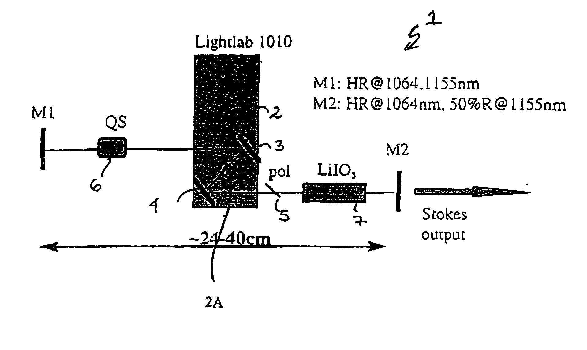
[0112] A 34 cm long cavity with a 30 cm radius of curvature high reflector, M1, a flat output coupler, M2, with near-optimum transmission at the fundamental of 12% and an aperture (750 .mu.m diameter) to confine oscillation to the TEM.sub.00 mode was used (for diode currents up to 18A the fundamental beam profile is generally singly moded and fairly free of aberration, as the diode current is increased however the fundamental profile generally becomes strongly aberrated and may consist of several transverse modes however the Stokes output almost always occurs in a single traverse mode (TEM.sub.00) indicating Raman beam-cleanup). The output power at 1064 nm was in the range 5.5-6.6W at the maximum diode operating current (25A) depending on the exact Q-switch repetition frequency. The optimally-coupled conditions at 1064 nm in this experiment provide the optimum performance baseline to which the output from the Raman laser is compared in order to evaluate optical to optical conversion...

experiment 2

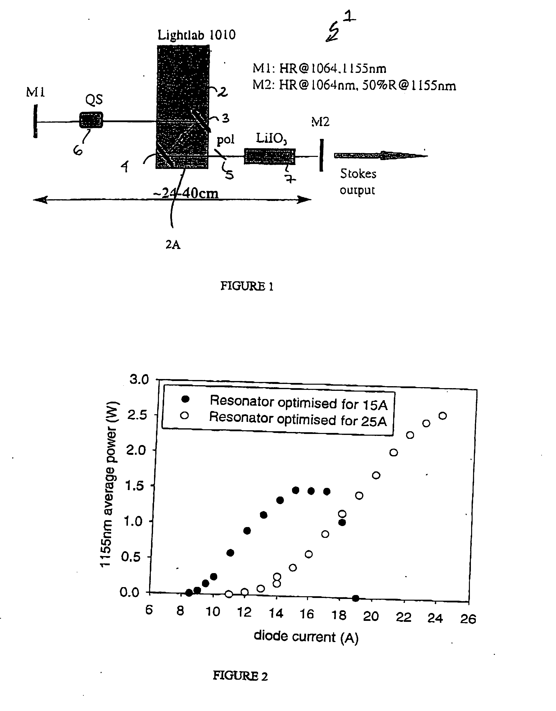
[0114] The Raman resonator cavities were optimised for the highest Stokes output at a specific diode current. The optimisation was basically empirical, a variety of resonators were evaluated using a variety of combinations of cavity lengths, mirror curvatures, output couplings and positioning of the key cavity elements. FIG. 2 shows the measured output power of the Raman laser at approximately 1155 nm using two separate cavity configurations optimised for operation at 15A and 25A diode current. In both cases a 5 cm length of LiIO.sub.3 was used.

[0115] The first resonator configuration optimised at 15A incorporated two flat end mirrors, the high reflectivity minor was placed 9.5 cm and the output coupler (50% transmitting) placed 12 cm from the centre of the pump module. A maximum power of 1.45W at 1155 nm was obtained at 10 kHz corresponding to a conversion efficiency of 57% (78% accounting for collection efficiency) with respect to the base laser performance at 1064 nm (2.6W). As t...

experiment 3

[0119] A number of Raman Laser parameters were studied. A resonator was used consisting of a 30 cm concave highly reflecting mirror placed about 25 cm from the centre of the pump module and a flat output coupler placed 8 cm from the pump module. The LiIO.sub.3 was placed close to the pump module where the resonator mode was largest (approximately 320 .mu.m). A maximum output of 2.3W at a first Stokes wavelength was obtained with this cavity configuration slightly lower than for the 25A resonator of Experiment 2 but with a far lower incidence of crystal damage.

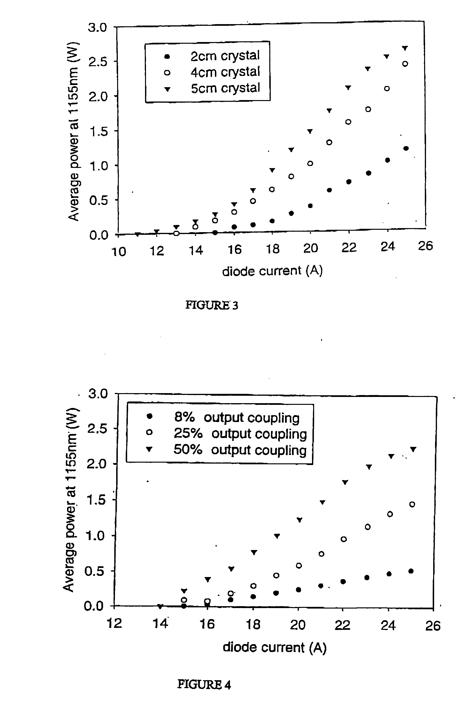
[0120] In FIG. 3 the average power of the first Stokes wavelength as a function of diode current for crystal lengths 2, 4 and 5 cm was studied. Te pulse repetition frequency was 15 kHz and a 50% transmitting output coupler was used. Higher output powers were achieved with longer crystals as expected since Raman gain coefficient is proportional to the length of the Raman gain medium. The output at 1155 nm obtained using the 4 cm...


PUM

PropertyMeasurementUnit
wavelengthaaaaaaaaaa

Abstract

The present invention relates to a stable solid-state Raman laser (1), the solid-state Raman laser including: (a) a resonator cavity defined by at least two reflectors (M1 and M2), (b) a laser material (2A) located in the resonator cavity and capable of generating a cavity laser beam which propagates within the resonator cavity, (c) a solid Raman medium (7) located in the resonator cavity for shifting the frequency of the cavity laser beam to produce a Raman laser beam which propagates within the resonator cavity; and (d) an output coupler (M2) for coupling and outputting the Raman laser beam from the resonator cavity, wherein at least one parameter selected from the group consisting of (i) the position of the laser material (2A) relative to the position of the Raman medium (7) in the cavity, (ii) the length of the cavity and (iii) the curvature of at least one of the reflectors (M1 or M2), is selected such that changes in the focal lengths of both the laser material (2A) and the Raman medium (7) as a result of thermal effects in the laser material (2A) and the Raman medium (7) during operation of the laser do not substantially cause instability in the power of the output Raman laser beam. A method of maintaining stable operation of a solid state Raman laser is also described.

Description

[0001] The present invention relates to a stable solid-state Raman laser and a method of maintaining stable operation of a solid-state Raman laser.[0002] Solid-state Raman lasers are a practical and efficient approach to optical frequency down conversion offering high (up to 70-80%) conversion efficiencies with respect to the pump laser power, excellent beam quality and ease of alignment In recent years use of crystals for stimulated Raman scattering (SRS) has been gaining interest because, in comparison with high-pressure gaseous and dye (liquid) Raman lasers, crystalline Raman lasers offer better gain, better thermal and mechanical properties, better reliability and the ability to operate at high pulse-repetition frequency. Further they are compatible with compact all-solid state laser technology.[0003] The potential of crystalline Raman lasers for efficient frequency conversion was first reported by E. O. Ammann and C. D. Dekker, "0.9 W Raman oscillator", J. Appl. Phys., vol. 48,...

Claims


Application Information

Patent Timeline
Patent Type & Authority Applications(United States)
IPC IPC(8): G02F1/37G02F1/35H01S3/08H01S3/108H01S3/109H01S3/11H01S3/113H01S3/136H01S3/139H01S3/30
CPCH01S3/08072H01S3/108H01S3/30H01S3/136H01S3/139H01S3/117
Inventor PASK, HELEN M.PIPER, JAMES A.
Owner MACQUARIE UNIV
Why Eureka
Try Eureka