
Charging apparatus for lead storage battery

a technology of lead storage batteries and charging apparatuses, which is applied in the direction of dc-dc conversion, transportation and packaging, and power electronics conversion efficiency, can solve the problems of reducing charging efficiency, reducing charging efficiency, and complicated circuit configuration, and achieves simple apparatus configuration and easy adjustment of charging curren

Active Publication Date: 2014-01-30
DAIFUKU CO LTD
View PDF8 Cites 22 Cited by
  • Summary
  • Abstract
  • Description
  • Claims
  • Application Information

AI Technical Summary

Benefits of technology

The present invention is a charging apparatus for a lead storage battery that uses a pulse charging method. The apparatus has a simple configuration and allows for easy adjustment of the charging current. The apparatus does not require a smoothing circuit and uses a DC choke to avoid noise. An optimum current can be obtained for pulse charging based on the turns ratio of the insulating transformer, and the size and cost of the insulating transformer can be reduced. Overall, the invention provides a cost-effective and efficient solution for pulse charging of lead storage batteries.

Problems solved by technology

An object of the method of charging a lead storage battery in Japanese Patent No. 4068268 is to solve a problem, “in a quick charge method using a relatively large constant current of at least 1.0 C, a battery voltage reaches at least a gas generating voltage and generates oxygen gas and hydrogen gas before charging of a sufficient amount, leading to a reduction in charging efficiency and degradation of life characteristics”.
According to this method, when a battery is charged to a certain degree, polarization components rapidly increase a voltage to at least a gas generation voltage and gas is generated from electrodes during energization, reducing charging efficiency.
However, the known method of charging a lead storage battery does not disclose a charging apparatus, that is, a specific method of generating a pulse specified by the energization time T1 and the stop time T2 with a constant current of at least 1.0 C. Specifically, for example, assuming that 1 C of a lead storage battery is an ordinary current of 30 A, a charging apparatus that generates a pulse with a perfect square wave applies a current of at least 30 A (at least 1.0 C), e.g., 50 A for a time period of at least 0.005 seconds to less than 0.1 seconds and stops the current application for less than 0.1 seconds, resulting in a complicated circuit configuration.
Thus, it is actually difficult to achieve an inexpensive apparatus, leading to extremely high cost.

Method used


Image

  • Charging apparatus for lead storage battery
  • Charging apparatus for lead storage battery
  • Charging apparatus for lead storage battery

Examples


Embodiment Construction

[0022]An embodiment of the present invention will be described below with reference to the accompanying drawings.

[Basic Circuit]

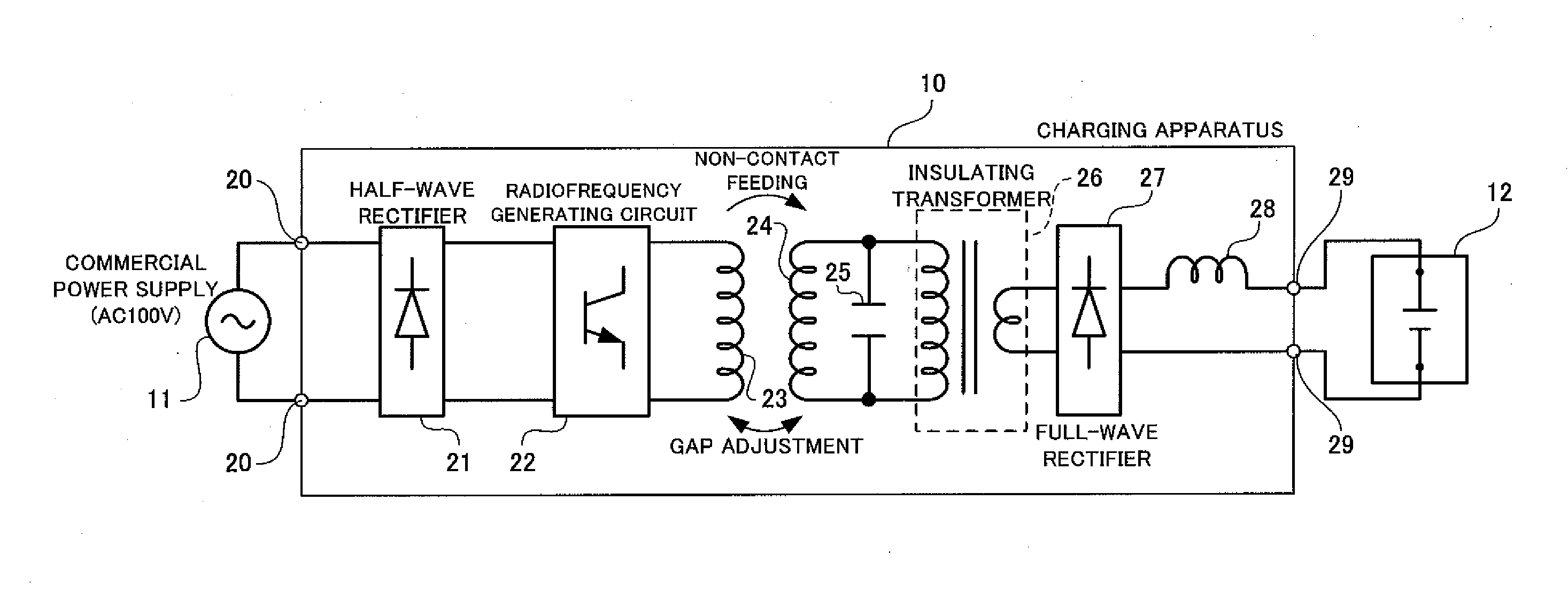
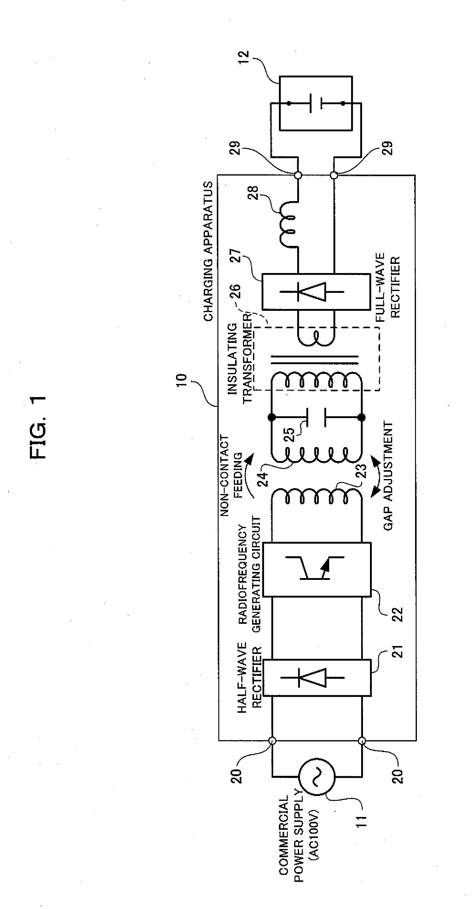
[0023]FIG. 1 is a basic circuit diagram illustrating a charging apparatus for a lead storage battery according to the embodiment of the present invention.

[0024]As illustrated in FIG. 1, a charging apparatus 10 for a lead storage battery is fed with power from a commercial power supply 11 and charges a lead storage battery 12. The charging apparatus 10 includes a feeding input terminal 20, a half-wave rectifier 21, a radiofrequency generating circuit 22, an induction coil 23, a power receiving coil 24, a resonant capacitor 25, an insulating transformer 26, a full-wave rectifier 27, a DC choke 28, and a charging output terminal 29.

[0025]Specifically, the charging apparatus 10 for the lead storage battery includes:

[0026]the feeding input terminal 20 connected to the AC commercial power supply 11;

[0027]the half-wave rectifier 21 that half-wave rectifies, to a d...


PUM


Abstract

A charging apparatus 10 includes: a half-wave rectifier 21 that half-wave rectifies an alternating current supplied from a commercial power supply 11; a radiofrequency generating circuit 22 that converts the output current of the half-wave rectifier 21 to a radiofrequency current with a predetermined frequency and outputs the radiofrequency current; an induction coil 23 that is fed with the radiofrequency current from the radiofrequency generating circuit 22; a power receiving coil 24 that receives an electromotive force induced by a magnetic flux produced on the induction coil 23; a resonant capacitor 25 that is connected in parallel with the power receiving coil 24 and forms a resonant circuit with the power receiving coil 24 at the predetermined frequency; and a full-wave rectifier 27 that full-wave rectifies the output current of the parallel resonant circuit and supplies the current to a lead storage battery 12.

Description

FIELD OF THE INVENTION[0001]The present invention relates to a charging apparatus for a lead storage battery and particularly relates to a charging apparatus that charges a lead storage battery installed in a mobile unit from an induction line.BACKGROUND OF THE INVENTION[0002]Japanese Patent No. 4068268 discloses an example of a known method of charging a lead storage battery.[0003]An object of the method of charging a lead storage battery in Japanese Patent No. 4068268 is to solve a problem, “in a quick charge method using a relatively large constant current of at least 1.0 C, a battery voltage reaches at least a gas generating voltage and generates oxygen gas and hydrogen gas before charging of a sufficient amount, leading to a reduction in charging efficiency and degradation of life characteristics”. The charging method is pulse charging in which a lead storage battery is charged by a constant current of at least 1.0 C for a predetermined energization time T1, and then the chargi...

Claims


Application Information

Patent Timeline
IPC IPC(8): H02J7/00
CPCH02J50/12H02J7/00711H02J7/02H02J2207/20H02M3/3382Y02B70/10H02J50/70
Inventor NISHINO, SHUZO
Owner DAIFUKU CO LTD
Learn More