
Firearm, aiming system therefor, method of operating the firearm and method of reducing the probability of missing a target

a technology of aiming system and firearm, applied in the field of aiming system, can solve the problems of low effectiveness of firearm, questionable verification of possible line of sight firing, and casualties of friendly soldiers, so as to reduce collateral damage, minimize casualties of civilian and friendly forces, and accurate firing

Active Publication Date: 2014-01-30
SMART SHOOTER
View PDF21 Cites 46 Cited by
  • Summary
  • Abstract
  • Description
  • Claims
  • Application Information

AI Technical Summary

Benefits of technology

The present invention is a firearm with an improved aiming system that can increase firing efficiency. It uses an imaging and processing system to accurately measure the range of a target and track it, even while the user is moving. This can help avoid accidental misses and reduce collateral damage. The firearm can also highlight and track multiple targets simultaneously, making it easier to fire at multiple targets without requiring the user to lock on to each target between rounds. The invention can help in various situations such as long range firefighting, physical effort, or while moving. It can help in training and debriefing, and saves ammunition. Overall, the invention provides accurate and safe firing without the need for barrel motion sensors.

Problems solved by technology

Firearms have a low effectiveness for a number of reasons, even in the case where a high quality firearm is used.
Some of the problems include movement (shaking) by the user (the main issue); movement of the target (e.g. a live target such as a combatant or criminal); relative aiming—such as the range to the target and inclination angle (ballistics), dynamic issues of the firearm (e.g. heating up of the barrel during use); atmospheric / ambient conditions (e.g. wind, fog, elevation, etc); and visualization of the target (i.e. the target may be temporarily hidden and not in a line of sight position for aiming) On the police force, it is common that most firing results in a miss; and in combat, the vast majority of firing results in a miss.
Furthermore, there are also frequent issues with friendly soldiers being killed or wounded by so called “friendly fire”.
However, the remote targeting device makes verification of possible line of sight firing questionable.

Method used


Image

  • Firearm, aiming system therefor, method of operating the firearm and method of reducing the probability of missing a target
  • Firearm, aiming system therefor, method of operating the firearm and method of reducing the probability of missing a target
  • Firearm, aiming system therefor, method of operating the firearm and method of reducing the probability of missing a target

Examples


Embodiment Construction

[0041]Illustrative embodiments of the invention are described below. In the interest of clarity, not all features / components of an actual implementation are necessarily described.

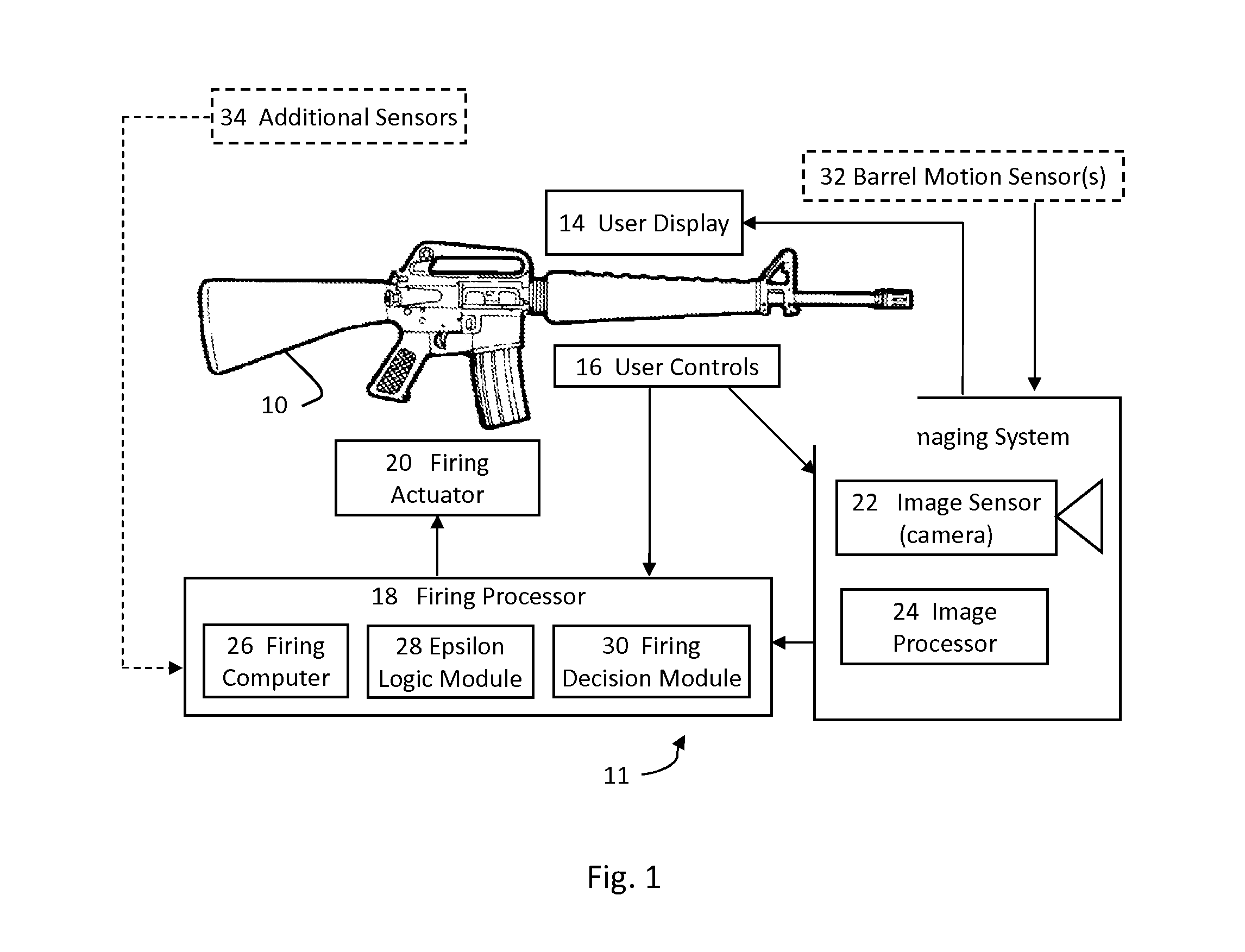
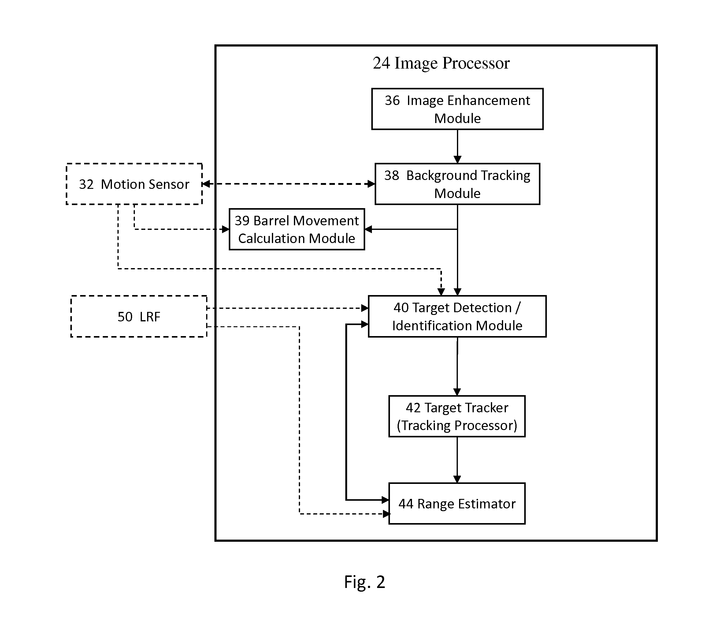
[0042]FIG. 1 shows an embodiment of a firearm 10 in schematic depiction comprising a firearm aiming system 11, the system adapted to allow the user to lock onto a target, or a plurality of targets and only allow firing if the aiming system determines the target will be hit. For such purpose the aiming system 11 comprises an imaging system 12; a user display 14; user controls 16, for locking / unlocking onto the target or targets; a firing processor 18 (described in more detail with respect to FIG. 2); and a firing actuator 20 to effect firing. Firing actuator 20 can be mechanical, electrical or electro-mechanical and enables or disables firing when the firearm's trigger is pressed or electronic firing means are used. However, typically aiming system 11 will include an override capability to allow “unhindered”...


PUM


Abstract

A firearm aiming system comprising an imaging system comprising an imaging sensor and an image processor; and a user display, wherein the imaging system is adapted to detect a potential target on the user display based on target features. In some embodiments the system includes a firing processor with an epsilon logic module for calculating a target aim-point / area used by the firing processor to make a firing decision.

Description

FIELD OF THE INVENTION[0001]The present invention relates to firearms, in particular an aiming system therefor.BACKGROUND OF THE INVENTION[0002]Firearms have a low effectiveness for a number of reasons, even in the case where a high quality firearm is used. Some of the problems include movement (shaking) by the user (the main issue); movement of the target (e.g. a live target such as a combatant or criminal); relative aiming—such as the range to the target and inclination angle (ballistics), dynamic issues of the firearm (e.g. heating up of the barrel during use); atmospheric / ambient conditions (e.g. wind, fog, elevation, etc); and visualization of the target (i.e. the target may be temporarily hidden and not in a line of sight position for aiming) On the police force, it is common that most firing results in a miss; and in combat, the vast majority of firing results in a miss. Furthermore, there are also frequent issues with friendly soldiers being killed or wounded by so called “f...

Claims


Application Information

Patent Timeline
IPC IPC(8): H04N5/232
CPCH04N5/23296F41A17/08F41G3/06F41G3/165F41G3/08F41G3/12H04N23/69
Inventor EHRLICH, AVSHALOM
Owner SMART SHOOTER
Learn More