
Imaging System And Method For Multi-Scale Three-Dimensional Deformation Or Profile Output

a three-dimensional deformation and profile technology, applied in the field of microscopy, can solve the problems of 2d imaging, high-accuracy 3d surface deformation and profile characterization at the micro-scale, and suffer from very limited measurement range, so as to suppress the chromatic dispersion of the diffraction grating

Active Publication Date: 2014-02-06
GEORGIA TECH RES CORP
View PDF3 Cites 14 Cited by
  • Summary
  • Abstract
  • Description
  • Claims
  • Application Information

AI Technical Summary

Benefits of technology

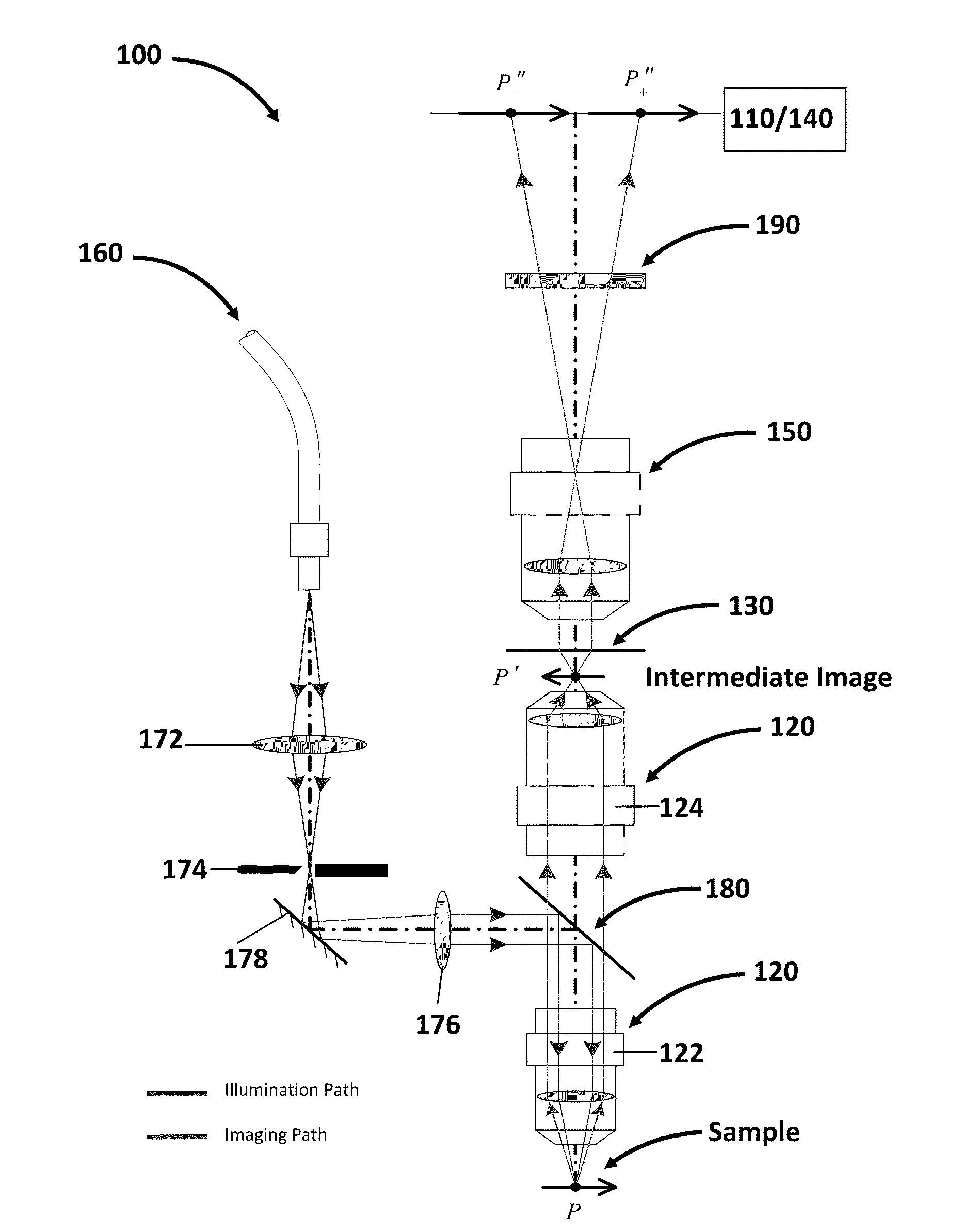
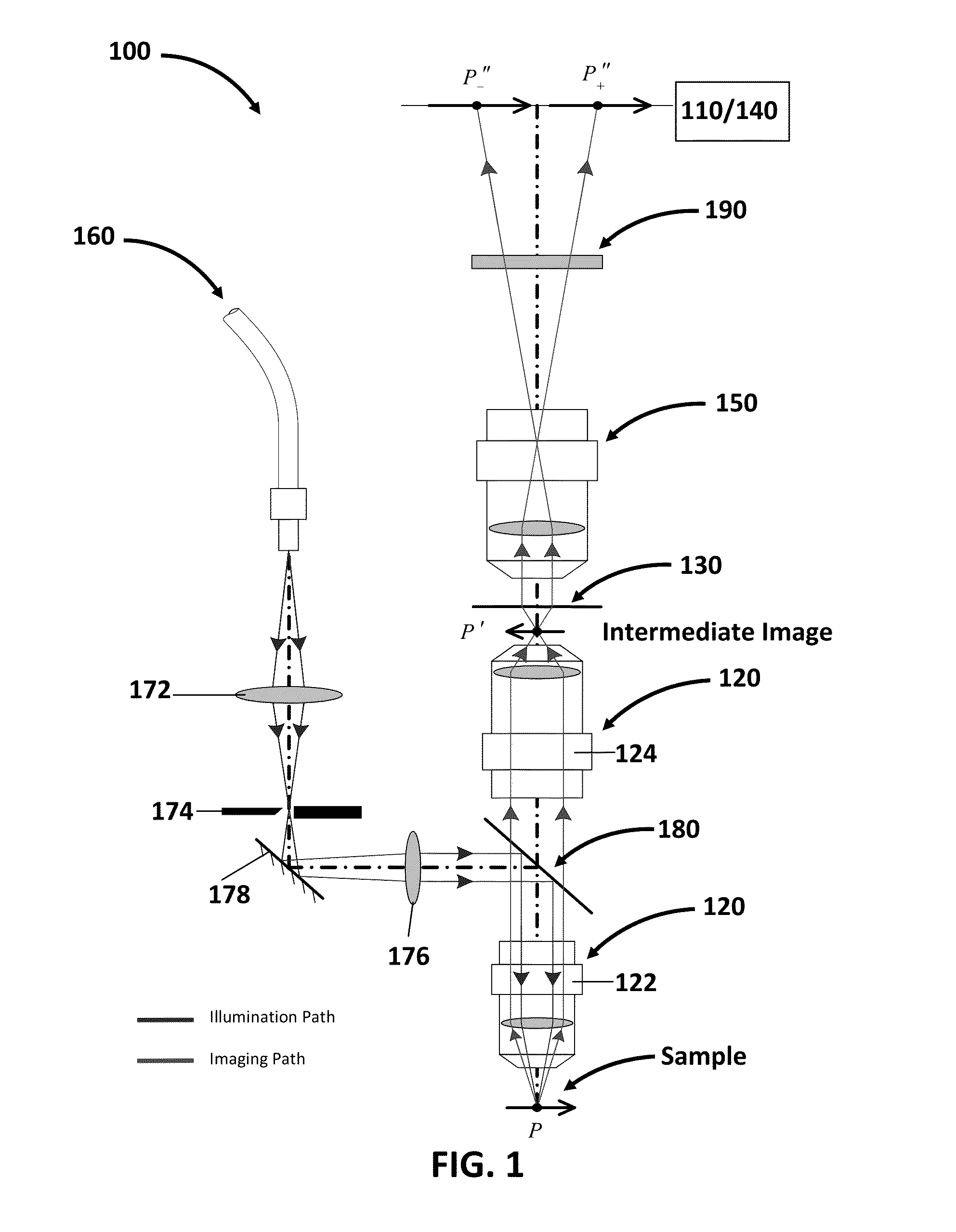
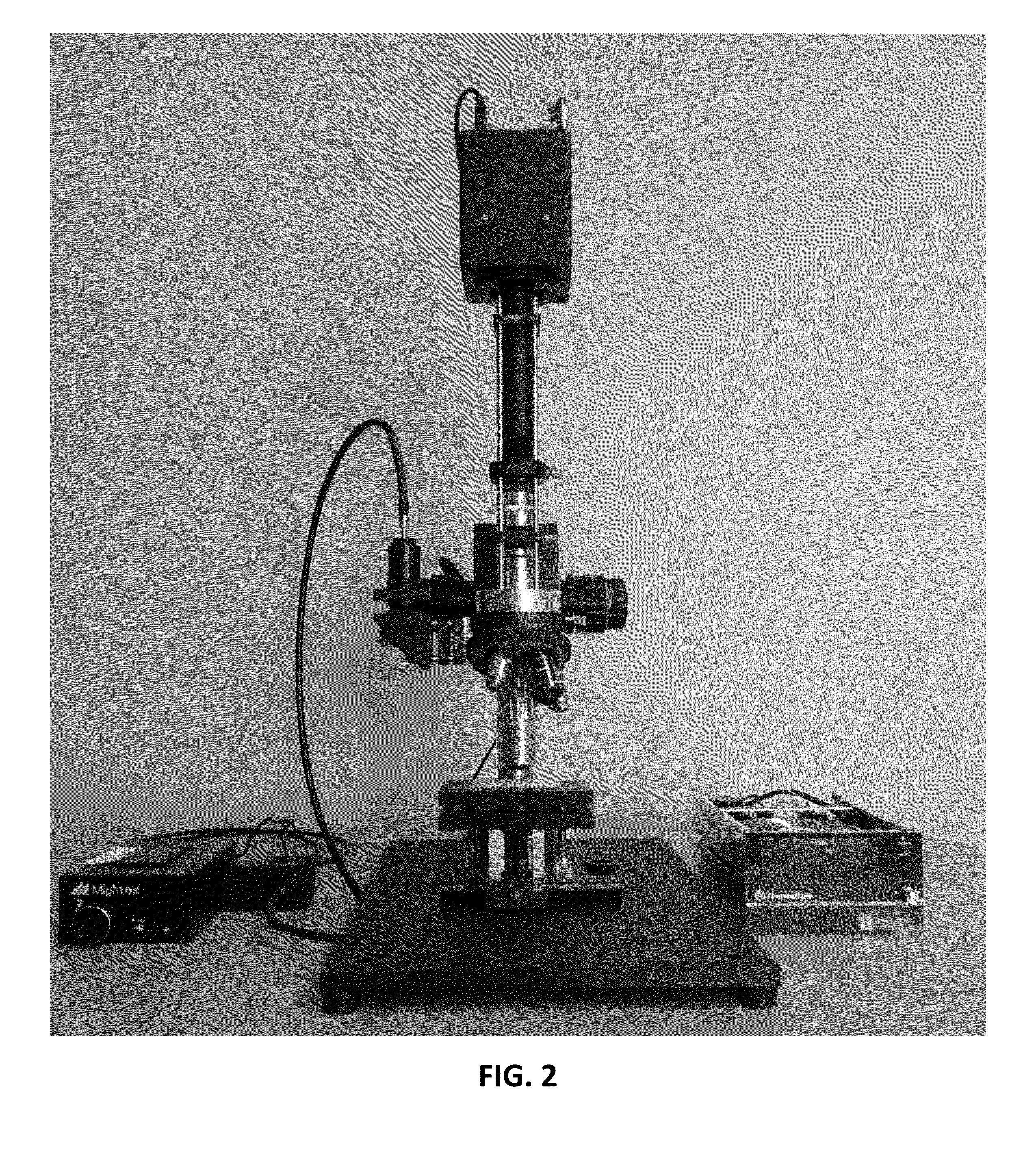
This patent describes a microscope objective that creates a high-resolution image of a micro-sized sample. A diffraction grating creates two virtual images of the sample, which are then projected onto a digital camera. The sample is patterned with fluorescent powder and illuminated with an ultraviolet LED light source. An iris diaphragm controls the size and location of the illuminated area, while a bandpass filter filters out background light and chromatic dispersion. The entire setup can be placed on a vibration isolation table to reduce external vibrations. The microscope objective can achieve different spatial resolutions for multi-scale characterizations. The invention provides high measurement accuracy and straightforward decoding of 3D information through 2D digital image correlation calculations.

Problems solved by technology

Among them, electronic speckle pattern interferometry (ESPI) offers the highest sensitivity, but suffers from very limited measurement range due to speckle decorrelation.
Despite the advent of the above measurement techniques, high-accuracy 3D surface deformation and profile characterizations at the micro-scale, however, remain a great challenge.
Traditional optical microscopes can achieve sub-micron spatial resolution, but they are only capable of 2D imaging.
It demonstrated the viability of the method through quantitative 3D imaging tests, but did not provide an imaging processing algorithm for quantitative 3D shape reconstruction.
While the traditional 3D-DIC combined with a stereo microscope has shown the capability to measure 3D deformation with micro-scale spatial resolution, the application of this technique to smaller length scales is hindered by the low-magnification power of stereo microscopy.

Method used


Image

  • Imaging System And Method For Multi-Scale Three-Dimensional Deformation Or Profile Output
  • Imaging System And Method For Multi-Scale Three-Dimensional Deformation Or Profile Output
  • Imaging System And Method For Multi-Scale Three-Dimensional Deformation Or Profile Output

Examples


Embodiment Construction

[0050]To facilitate an understanding of the principles and features of the various embodiments of the invention, various illustrative embodiments are explained below. Although exemplary embodiments of the invention are explained in detail, it is to be understood that other embodiments are contemplated. Accordingly, it is not intended that the invention is limited in its scope to the details of construction and arrangement of components set forth in the following description or illustrated in the drawings. The invention is capable of other embodiments and of being practiced or carried out in various ways. Also, in describing the exemplary embodiments, specific terminology will be resorted to for the sake of clarity.

[0051]It must also be noted that, as used in the specification and the appended claims, the singular forms “a,”“an” and “the” include plural references unless the context clearly dictates otherwise. For example, reference to a component is intended also to include composit...


PUM


Abstract

An optical microscope system for 3D surface deformation and morphology measurement that can serve as a powerful tool in quality engineering and control, as well as in biological and materials research is described. The system was developed in part by combining the DAIC technique with optical microscopy. Decoding algorithms were derived for calculating the 3D displacement or profile of a micro-sized test sample from the in-plane displacement components of it first-order diffracted views.

Description

CROSS-REFERENCE TO RELATED APPLICATIONS[0001]This application claims the benefit of US Provisional Application No. 61 / 677,535 filed 31 Jul. 2012, the entire contents and substance of which are hereby incorporated by reference.STATEMENT REGARDING FEDERALLY SPONSORED RESEARCH OR DEVELOPMENT[0002]N / ABACKGROUND OF THE INVENTION[0003]1. Field of Invention[0004]The present invention generally relates to the art of microscopy, and more particularly to a three-dimensional optical microscope for multi-scale deformation and shape measurement.[0005]2. Background and Related Art[0006]Three-dimensional (3D) full-field deformation and morphology analyses are widely used in many industrial and research applications. Driven by advances in biology and nanotechnology, there is a growing need for performing such analyses at the micro-scale. A good example in point is the study of deformation and failure mechanisms of complex material systems. Detailed experimental full-field characteristics, in combin...

Claims


Application Information

Patent Timeline
Patent Type & Authority Applications(United States)
IPC IPC(8): G02B21/36H04N13/02
CPCH04N13/0207G02B21/361G01B9/04G01B11/16G01B11/24G02B21/0016G02B27/1093G02B27/48H04N13/207
Inventor XIA, SHUMANZHANG, JINGWEN
Owner GEORGIA TECH RES CORP
Learn More