Connecting Mechanism for Medial and Lateral Polyethylene Bearing Surfaces for Knee Replacement

a technology of connecting mechanism and knee replacement, which is applied in the field of improved orthopedic implants, can solve the problems of significant increase in the chance of implant wear, implant failure and/or surgical error, and achieve the effects of improving the design of tibial inserts, facilitating the balancing of knee implants, and easy and effective connection

Inactive Publication Date: 2014-02-06
KURTZ WILLIAM B
View PDF6 Cites 19 Cited by
  • Summary
  • Abstract
  • Description
  • Claims
  • Application Information

AI Technical Summary

Benefits of technology

[0009]In various embodiments, the modular tibial inserts may be designed with an integrated frictional or other locking mechanisms, such as a dove-tail and / or lock-and-key mechanisms. The tibial insert locking mechanism can desirably allow the medial and lateral inserts to quickly mate and lock together. For example, a medial tibial insert may be desirably designed with a female docking cavity and a corresponding lateral tibial insert may be designed with the male extension that allows the lateral tibial insert to mate and slide together for a lock or engagement of the two pieces. The tibial insert lock mechanisms may include a variety of shapes, sizes and / or dimensions that may to obtain the best mechanical advantage for quick and strong locking of the medial and lateral tibial inserts and prevent mechanical failure of the joint.
[0010]In various embodiments, the modular tibial inserts may be designed with tibial insert mating and / or locking mechanisms, which can include a separate tibial insert locking tool or mating component that may be removable. For example, both the medial and lateral tibial inserts may be designed with female docking cavities, where the tibial lock tool slides within the medial and lateral docking cavities and mates the two pieces together for a frictional or other lock or engagement. The tibial insert lock mechanisms and the tibial locking tool may include a variety of shapes, sizes and / or dimensions that may to obtain the best mechanical advantage for quick and strong locking of the medial and lateral tibial inserts and prevent mechanical failure of the joint.
[0011]In various embodiments, the tibial locking tool may be designed with a tibial tray connector feature. The tibial locking tool with an integrated tibial tray connector can have dual functions—it may lock the medial and lateral tibial inserts together as well as lock the tibial insert assembly to the tibial tray. The tibial insert lock mechanism, the tibial locking tool and / or the tibial tray connector may include a variety of shapes, sizes and / or dimensions that may to obtain a mechanical advantage for quick and strong locking of the medial and lateral tibial inserts and / or the tibial tray to prevent mechanical failure of the joint.
[0012]In various embodiments, the modular tibial inserts with tibial insert friction lock mechanisms may be designed to attach to tibial trays with fixed-bearing features. In alternative embodiments, the modular tibial inserts with tibial insert friction lock mechanisms may be designed to attach to tibial trays with mobile-bearing features. Mobile-bearing features incorporated into a tibial tray design may facilitate more natural knee kinematics, in that the medial and lateral tibial inserts can be individually particularized while allowing the assembled insert to have multi-directional mobility, which may include rotation inside the tibial tray, anterior / posterior (A / P) movement, and / or medial / lateral (M / L) movement, and / or various combinations thereof.

Problems solved by technology

While such designs could potentially improve the ability of the surgeon to “balance” the patient's knee using appropriate combinations of medial and lateral inserts of different shapes, sizes and / or thicknesses that each secure into the tibial tray, the manipulation, positioning and maneuvering of multiple inserts in the knee joint can significantly increase the opportunity for implant wear, implant failure and / or surgical error.

Method used


Image

  • Connecting Mechanism for Medial and Lateral Polyethylene Bearing Surfaces for Knee Replacement
  • Connecting Mechanism for Medial and Lateral Polyethylene Bearing Surfaces for Knee Replacement
  • Connecting Mechanism for Medial and Lateral Polyethylene Bearing Surfaces for Knee Replacement

Examples


Embodiment Construction

[0037]The drawings and the following description relate to preferred embodiments by way of illustration only. It should be noted that from the following description, alternative embodiments of the components and methods disclosed herein will be readily recognizable as viable alternatives that may be employed in one skilled in the art.

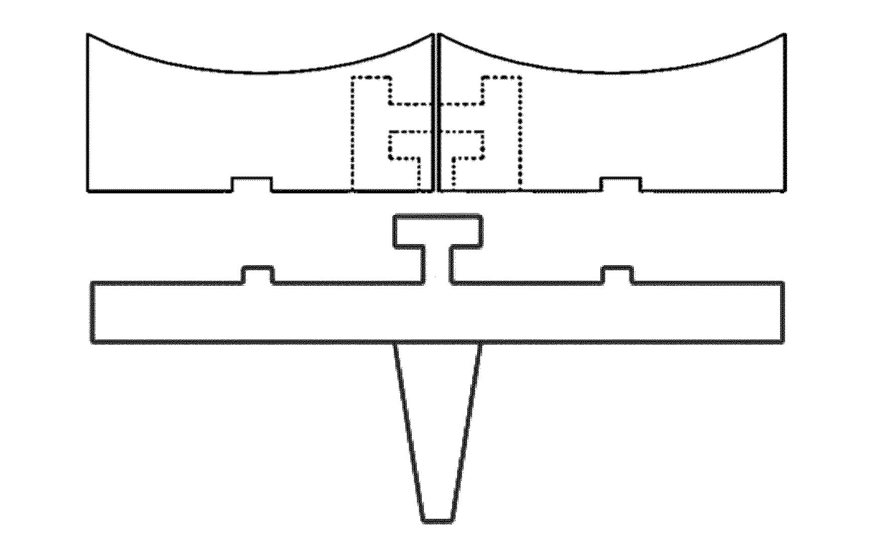
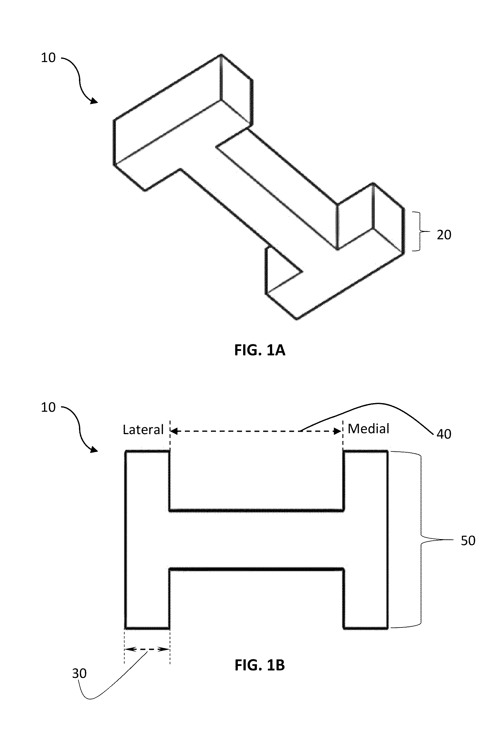
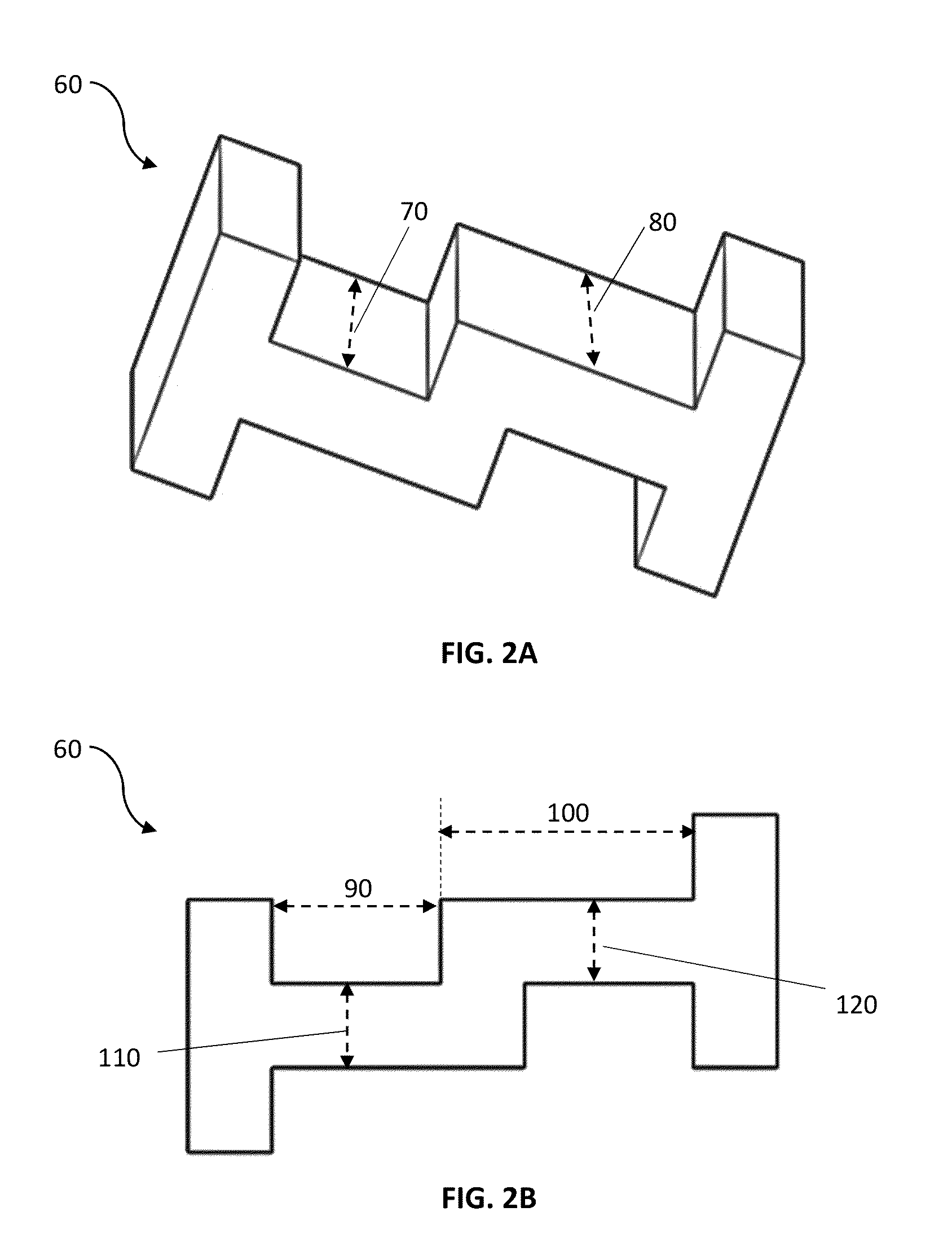
[0038]In one exemplary embodiment, the improved tibial implant component assembly may include a tibial locking tool, a medial tibial insert and a lateral tibial insert with a tibial insert locking mechanism, and a tibial tray with a tibial tray connector mechanism. In various embodiments the tibial tray may include fixed-bearing and / or mobile-bearing connection features for the assembled insert.

Tibial Insert Selection and Mating

[0039]In various embodiments, a plurality of tibial inserts of different sizes, shapes, materials and / or other physical features (with some variations between each of the inserts) can be provided to a surgeon as part of an implan...


PUM


Abstract

Disclosed herein are improved methods, apparatus and / or systems for a tibial implant assembly that can facilitate balancing, positioning, insertion, locking and maneuvering of the modular tibial inserts during knee surgery. The system may include a plurality of modular tibial inserts with locking or engagement mechanisms that allow creation of a modular insert assembly, and a corresponding tibial tray and optional tray components. The system allows the quick and convenient mating and locking of the tibial insert assembly to the tibial tray. The various components can accommodate mobile-bearing and fixed-bearing designs for the tibial tray.

Description

CROSS-REFERENCE TO RELATED APPLICATIONS[0001]This application claims the benefit of U.S. Provisional Patent Application Ser. No. 61 / 678,189 entitled “Connecting Mechanism for Medial and Lateral Polyethylene Bearing Surfaces for Knee Replacement,” filed Aug. 1, 2012. The disclosure of this document is incorporated by reference in its entirety.TECHNICAL FIELD[0002]The invention relates to improved orthopedic implants for use during a joint replacement procedure. More specifically, disclosed herein are improved methods, apparatus, and / or systems for a tibial implant component system that facilitate the adaptability and reliability of the system during surgery, including more accurately restoring normal kinematics in the knee, reducing the risk of implant failure and / or component dislocation and decreasing implant wear.BACKGROUND OF THE INVENTION[0003]In a typical knee joint replacement procedure, a surgical implant can include one or more metal, plastic or ceramic “base” components tha...

Claims


Application Information

Patent Timeline
Patent Type & Authority Applications(United States)
IPC IPC(8): A61F2/38
CPCA61F2/389A61F2002/30387A61F2002/30616A61F2/3868
Inventor KURTZ, WILLIAM B.
Owner KURTZ WILLIAM B
Why Eureka
Try Eureka