Multi-layer mold coating

a multi-layer mold and coating technology, applied in the direction of superimposed coating process, manufacturing tools, shaping tools, etc., can solve the problems of extending the reducing the service life of the tool piece, so as to achieve low friction, prolong the mold life, and reduce the effect of friction

Active Publication Date: 2014-02-13
HYUNDAI MOTOR CO LTD
View PDF0 Cites 8 Cited by
  • Summary
  • Abstract
  • Description
  • Claims
  • Application Information

AI Technical Summary

Benefits of technology

[0010]The present invention provides a multi-layer mold for use in forming ultra-high strength steel. According to the techniques described herein, a multi-layer mold may be formed by coating the surface of the mold with CrN or Ti(C)N, a TiAlN / CrN nano multilayer, and a TiAlCN / CrCN nano multilayer, which may provide heat resistance, oxidation resistance, abrasion resistance, and low friction characteristics to the tool piece (e.g., a mold), and also greatly extend the lifespan of the mold.
[0011]In one aspect, the present invention provides a multi-layer mold comprising: a CrN or Ti(C)N junction layer coated on a base material of the mold; a first TiAlN / CrN nano multi-layer coated on the CrN or Ti(C)N junction layer as an intermediate layer; and a second TiAlCN / CrCN nano multi-layer coated on the first TiAlN / CrN nano multi-layer as an outermost surface layer including carbon (C) of about 1 at.% to about 30 at. % for high temperature and low friction.

Problems solved by technology

Such tool pieces are subject to extreme wear during the metal working process.
Consequently, typical mold coating materials are deficient in durability and abrasion resistance when used to form steel sheets with a tensile strength of 980 MPa or more.
In other words, a major disadvantage of conventional coating materials is that they provide a tool piece lifespan of only about 50,000 press strokes or less, after which the coating layer is exfoliated from the surface of the tool piece (e.g., the mold).
Another disadvantage of conventional coating materials is that many require the use of a lubricant during the steel sheet forming process.
For example, coating materials such as TiAlN and Al TiCrN+MoS2 typically require the use of a drawing oil due to deficiency of durability of the coated tool piece.
While the use of a lubricant allows friction and abrasion to be temporarily reduced, the drawing oil may introduce impurities into the steel sheet that may negatively affect a subsequent process, e.g., a welding process, causing a reduction in the quality of the molded products.

Method used


Image

  • Multi-layer mold coating
  • Multi-layer mold coating
  • Multi-layer mold coating

Examples


example

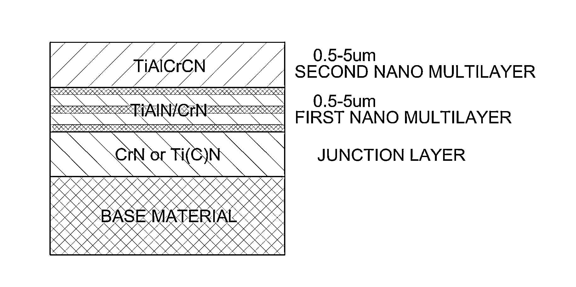
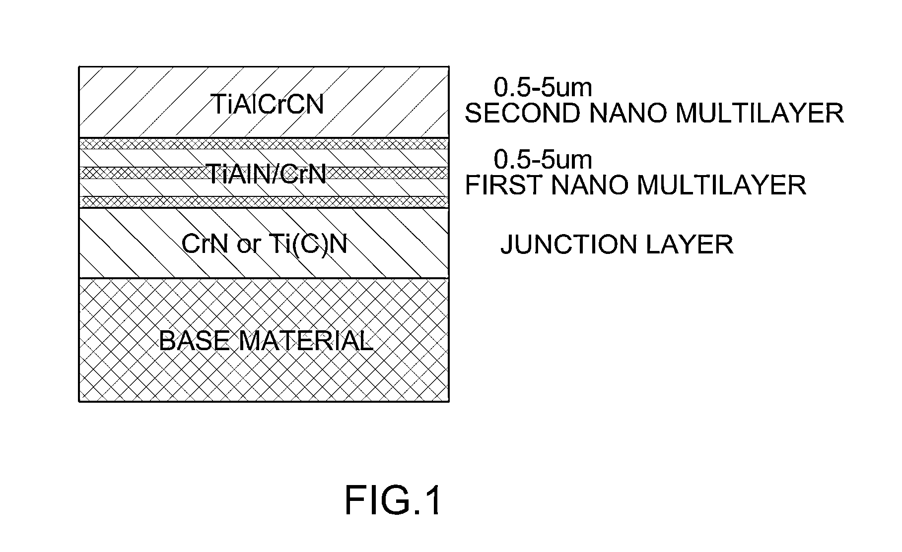
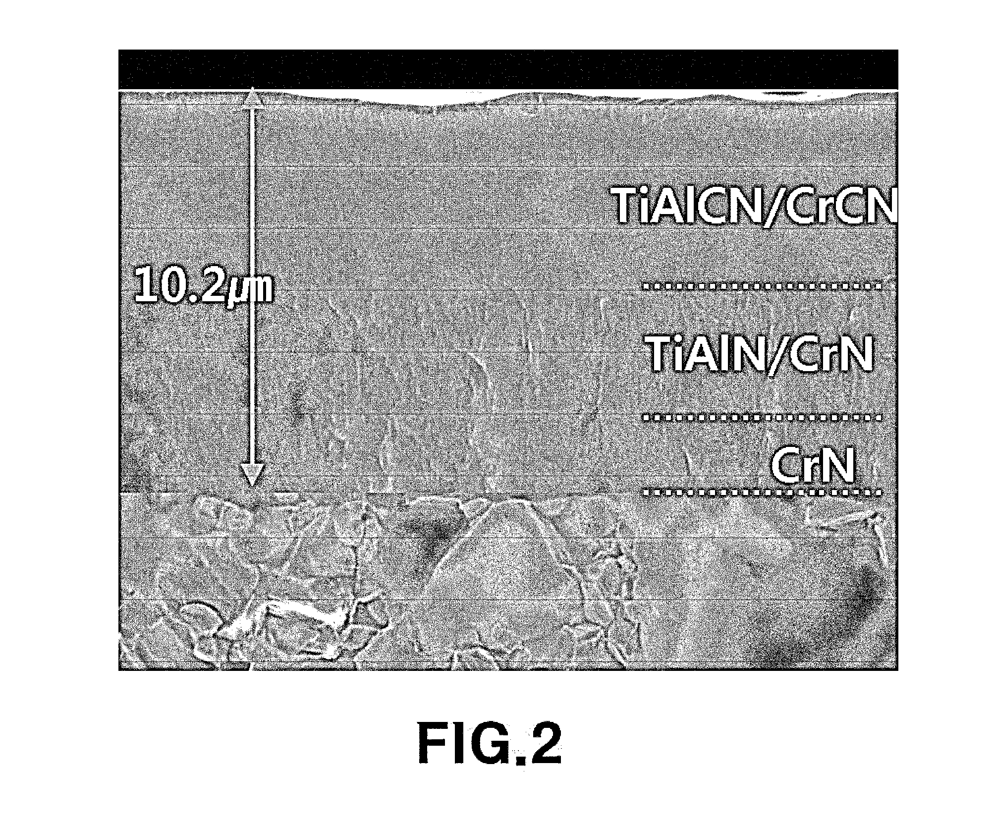
[0040]As shown in Table 1 below, a CrN junction layer may be coated on the surface of a mold base material in a thickness of about 4.9 μm by the above described PVD method, and then a first TiAlCrN nano multilayer may be coated on the CrN junction layer in a thickness of about 4.2 μm. Thereafter, a second TiAlCrCN nano multilayer may be coated as the uppermost surface layer in a thickness of about 1.1 μm. The resulting coating texture is shown in FIG. 2.

TABLE 1Comp. Comp. Comp. Comp. Ex. 1 Ex. 2 Ex. 3 Ex. 4 Embodiment SurfaceVC TiAlN AlCrN AlTiCrN4—MoS2 TiAlCrCNtreatment /  Coating Method TD PVD PVD PVD(+Spraying) PVD Thickness8.4 9.5 9.8 9.5 10.2 (μm) (SCrN—4.5TiAlN) (SCrN—4.8AlCrN) (4.9CrN—4.6AlTiCrN) +(4.9CrN / 4.2TiAlCrN—1.1TiAlCrCN) 20 μm MoS2 


PUM

PropertyMeasurementUnit
thicknessaaaaaaaaaa
thicknessaaaaaaaaaa
tensile strengthaaaaaaaaaa

Abstract

The present disclosure provides a multi-layer tool piece coating. For example, the tool piece may be a mold or die used for forming ultra high strength steel sheet. The multi-layer mold coating may include a CrN or Ti(C)N junction layer, a first TiAlN / CrN nano multilayer, and a second TiAlCN / CrCN nano multilayer. The CrN or Ti(C)N junction layer may be coated on a base material of the tool piece (e.g., a mold) for forming the steel sheet. The first TiAlN / CrN nano multilayer may be coated on the CrN or Ti(C)N junction layer as an intermediate layer. The second TiAlCN / CrCN nano multilayer may be coated on the first TiAlN / CrN nano multilayer as an outermost surface functional layer, and may include carbon (C) of about 1 at. % to about 30 at. % for high temperature and low friction.

Description

CROSS-REFERENCE TO RELATED APPLICATION[0001]This application claims under 35 U.S.C. §119(a) the benefit of Korean Patent Application No. 10-2012-0086217 filed Aug. 7, 2012, the entire contents of which are incorporated herein by reference.BACKGROUND[0002](a) Technical Field[0003]The present invention relates to a multi-layer mold coating material for use in forming an ultra-high strength steel sheet. More particularly, the present invention relates to a multi-layer mold coating material for forming an ultra-high strength steel sheet that provides heat resistance, abrasion resistance, and low friction characteristics to the surface of the mold.[0004](b) Background Art[0005]Steel sheet may be formed by a variety of processes such as, for example, deep drawing, incremental sheet forming, punching, rolling, stamping, etc. These processes typically require a tool piece (e.g., a mold, a die, punch, etc.) in order to form the steel sheet. Such tool pieces are subject to extreme wear during...

Claims


Application Information

Patent Timeline
Patent Type & Authority Applications(United States)
IPC IPC(8): B21D37/14
CPCB32B15/01C23C14/0641C23C14/0664C23C28/042C23C28/044C23C28/42B21D37/00C23C14/06C23C14/34
Inventor CHA, SUNG CHUL
Owner HYUNDAI MOTOR CO LTD
Why Eureka
Try Eureka