Condition 1), instead, has proven to be difficult to fulfil by employing the known techniques.
If the container handling
machine were moved by a computer without knowing the real location or travel direction, a danger would arise of the container handling
machine colliding with containers, other cranes or other buildings possibly residing along the planned
route.
If in the depot field the operator of the container handling
machine takes the container 1 to a location 6 different from what is assumed by the TOS or, alternatively, the operator of the container handling machine enters into the TOS an erroneous location of the container, it will be problematic to find the container in the container depot field later.
In particular, if the container has to be looked for in the depot field while a ship is being loaded, the costs become very high because the aim is expressly to minimize the unloading and loading times of ships in ports.
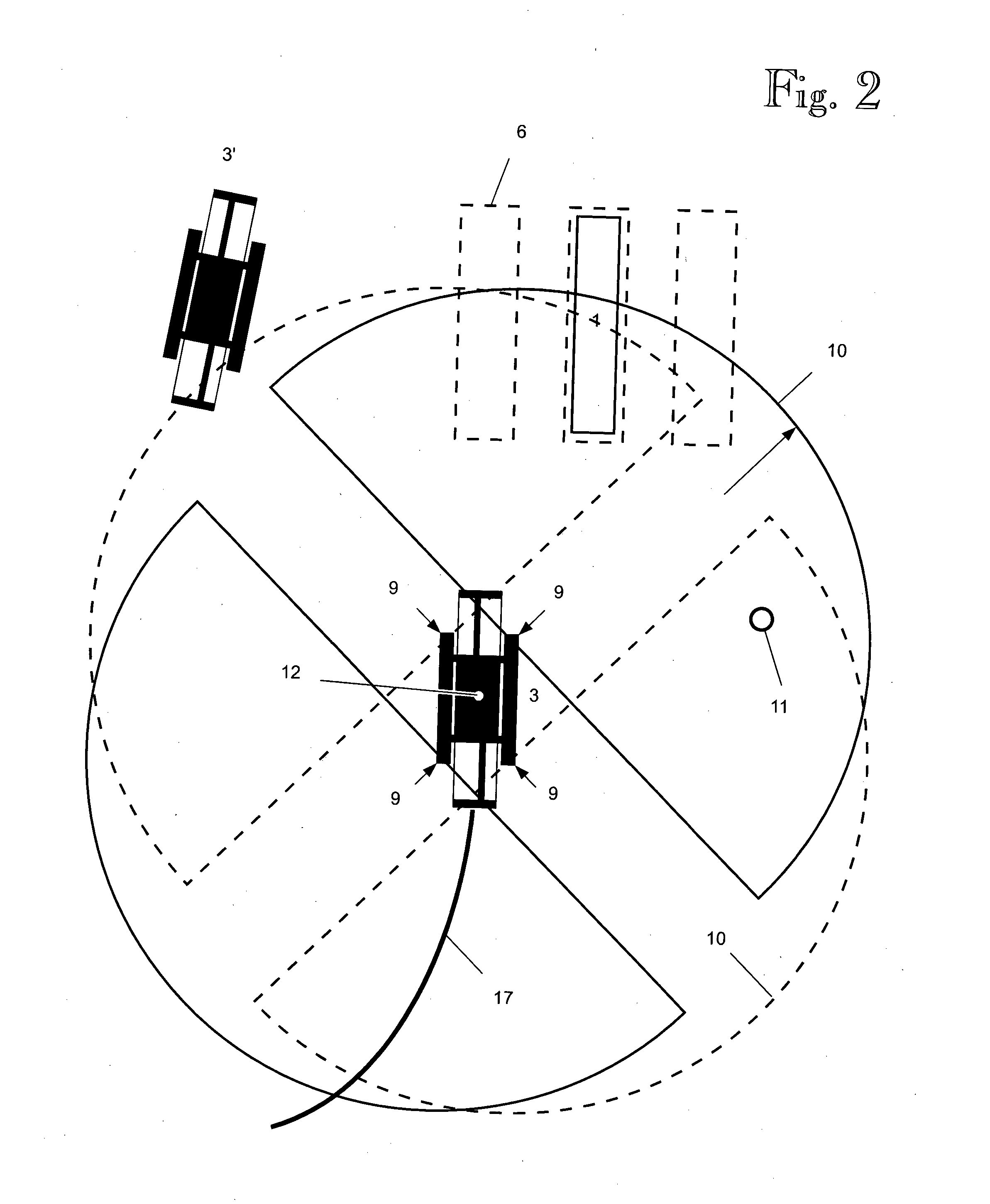
However, the
GPS positioning technology does not work reliably within the entire port area since the GPS device antenna 12 has to maintain
visual communication typically to at least five
GPS satellites simultaneously in order to be able to calculate a location reliably.
Large container cranes 3, such as a ship crane 4, prevent GPS radio signals from propagating therethrough free of interference, thus causing shadow areas and a decrease in accuracy in the
GPS positioning.
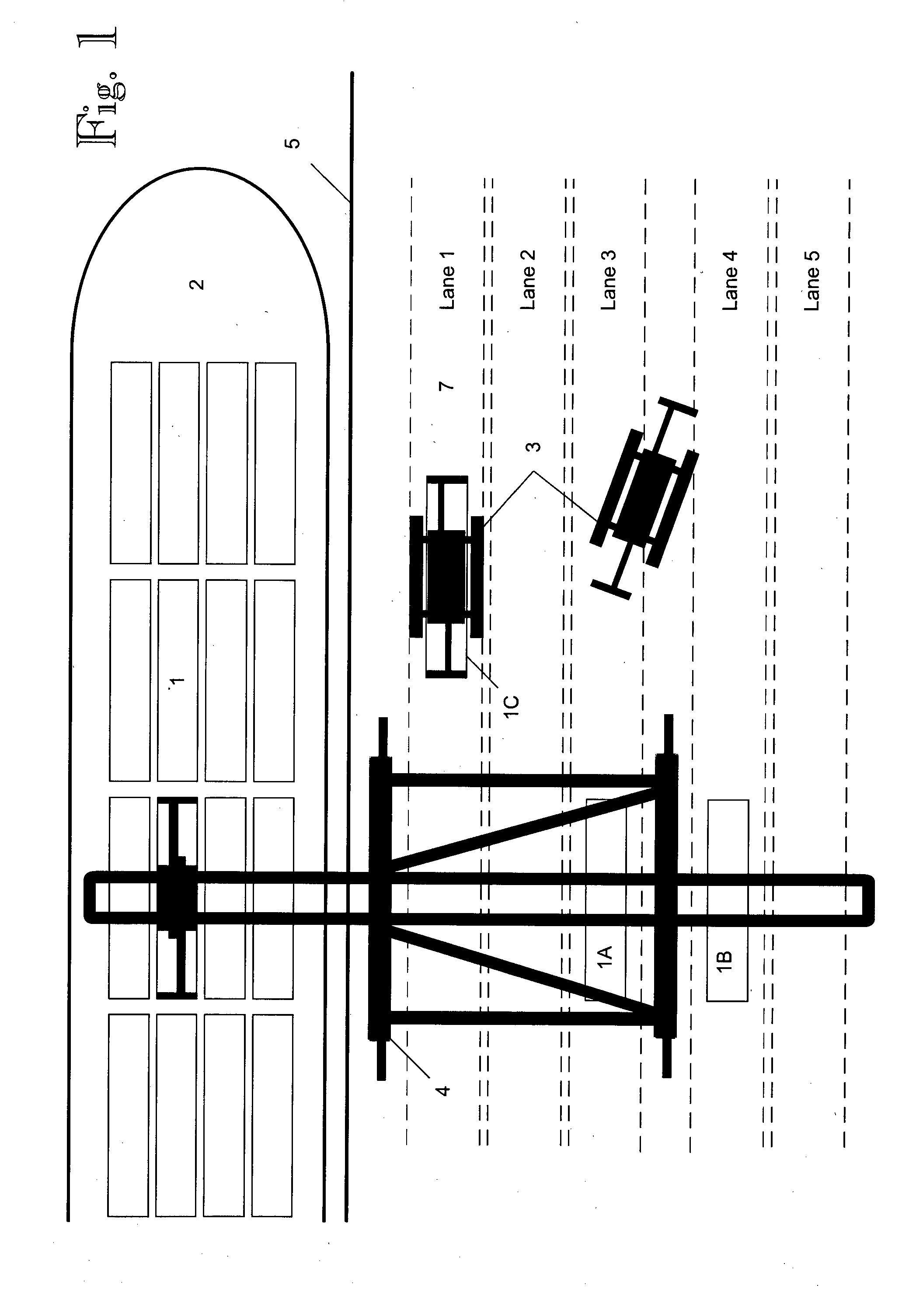
For instance, it is impossible for the GPS technology to reliably detect in which location or in which lane 7 in particular (cf. FIG. 1) beneath a ship crane the container handling machine 3 leaves a container, or from which lane the container handling machine picks up a container.
A similar problem occurs when
GPS positioning is used in the vicinity of or beneath other large container cranes 3 (e.g. RTG or RMG cranes).
When unloading a ship, for instance, a particular problem is presented by a situation wherein more than one container has been laid onto the ground on the quay, e.g. in adjacent lanes, by the ship crane 4.
If no positioning data from the container handling machine is available, it is then impossible to know for sure which one of the containers the container handling machine 3 arriving beneath the crane picks up.
Consequently, it is also impossible to know for sure in which locations in the container deposit the containers 1A and 1B eventually end up, thus making it impossible to automatically monitor the location of the containers.
Similarly, when loading a ship, it is impossible to know for sure in which lane the container handling machine 3 leaves a container.
In such a case, it is impossible to automatically ensure that the container 1C becomes loaded correctly
on board the ship.
Furthermore, anyone present on the quay is not only an additional cost factor but also a possible presenter of danger situations since accidents happen in ports, even killing people run over by a container handling machine.
However, the publication discloses no working techniques for positioning a vehicle at all but incorrect conclusions are systematically made from
location determination.
The techniques of EP 0185816 A1 based on
triangulation could work if the directions from the vehicle to the landmarks were absolute directions bound to the ground but, as the vehicle turns with respect to the ground, this is not the case.
Since the position of the vehicle is unknown, the techniques of EP 0185816 A1 systematically suffer from the problem that there are more unknown than known factors, making groups of equations—were such presented—impossible to solve.

