Angular acceleration detection device

a detection device and angular acceleration technology, applied in the direction of acceleration measurement using interia forces, turn-sensitive devices, instruments, etc., can solve the problems of reducing the stress generated in each support beam per unit of angular acceleration, and reducing the detection accuracy of angular acceleration. , to achieve the effect of preventing the concentration of stress, increasing the stress generated in the support beam, and resisting the impa

Active Publication Date: 2014-02-20
MURATA MFG CO LTD
View PDF8 Cites 4 Cited by
  • Summary
  • Abstract
  • Description
  • Claims
  • Application Information

AI Technical Summary

Benefits of technology

[0019]In the rotating weight of the above-described type, a moment of inertia about the short axis is relatively large, and a rotational inertial force caused by disturbance vibration about the short axis is also relatively large. Accordingly, if the direction of length of the support beam is set to be the direction of the short axis of the rotating weight, the support beam would be twisted by the rotational inertial force about the short axis, and excessive stress would be concentrated in edge portions of the support beam. Hence, impact resisting performance would degrade. By setting the direction of length of the support beam to be the direction of the long axis of the rotating weight as described above, the support beam

Problems solved by technology

In such a case, the translational inertial force becomes a factor of increasing noise of the detection signal, and detection accuracy of the angular acceleration about the detection axis degrades.
In the related art described above, because the plural support beams bear, in a distributed manner, the inertial force exerted on the rotating weight, there has been a problem that, when the angular acceleration detection device is constit

Method used


Image

  • Angular acceleration detection device
  • Angular acceleration detection device
  • Angular acceleration detection device

Examples


first preferred embodiment

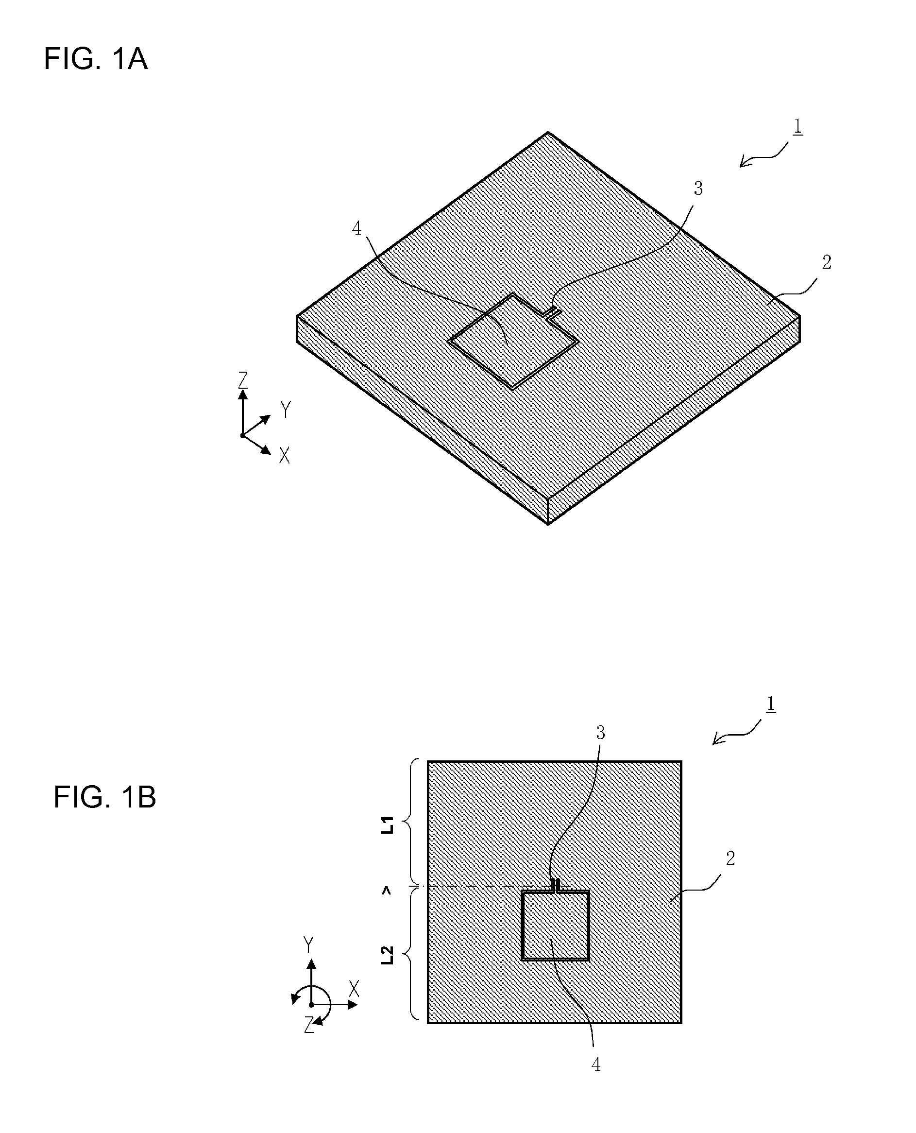
[0048]FIG. 1A is a perspective view illustrating a configuration of an angular acceleration detection device 1 according to a first preferred embodiment of the present invention, and FIG. 1B is a plan view of the angular acceleration detection device 1.

[0049]The angular acceleration detection device 1 preferably includes an integral rectangular or substantially rectangular plate provided with a groove penetrating through the plate between upper and lower surfaces thereof, which are perpendicular to the Z-axis. The angular acceleration detection device 1 includes a rotating weight 2, a support beam 3, a fixed portion 4, and a detection portion 5 (not illustrated in FIG. 1). The plate is obtained preferably by cutting a semiconductor wafer with surface machining. In the field of surface machining of a semiconductor wafer, performance of machining techniques and machining apparatuses are highly developed, and a plurality of plates can be efficiently manufactured with high accuracy.

[005...

second preferred embodiment

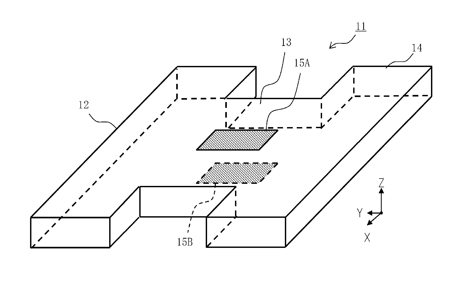
[0087]FIG. 6A is a perspective view of an angular acceleration detection device 11, in a deformed state, according to a second preferred embodiment of the present invention. FIG. 6B is a schematic view illustrating a structure around a support beam 13 of the angular acceleration detection device 11.

[0088]The angular acceleration detection device 11 includes a rotating weight 12, a support beam 13, a fixed portion 14, and a detection portion 15 (not illustrated). The rotating weight 12, the support beam 13, and the fixed portion 14 can be constituted substantially in the same structures as those in the first preferred embodiment. The second preferred embodiment is mainly different from the first preferred embodiment in that the piezoresistances 5A and 5B disposed in the detection portion 15 (not illustrated) are arranged at upper and lower surfaces of the support beam 13, respectively, and that the angular acceleration is detected with the X-axis serving as the detection axis.

[0089]F...

third preferred embodiment

[0092]FIG. 8 is a perspective view illustrating a configuration of an angular acceleration detection device 91 according to a third preferred embodiment of the present invention.

[0093]The angular acceleration detection device 91 preferably includes a rectangular or substantially rectangular plate provided with a groove penetrating through the plate between upper and lower surfaces thereof, which are perpendicular or substantially rectangular to the Z-axis. The angular acceleration detection device 91 includes a rotating weight 92, a support beam 93, a fixed portion 94, and a detection portion 95 (not illustrated). The rotating weight 92 preferably has a substantially elongated C-shaped configuration that is opened in the positive direction of the Y-axis. A long axis of the rotating weight 92 is set to be the X-axis direction, and a short axis thereof is set to be the Y-axis direction. The support beam 93 has a center aligned with a gravity center position of the rotating weight 92. ...


PUM


Abstract

An angular acceleration detection device includes a rotating weight, a fixed portion, a support beam, and a detection portion. The rotating weight is rotatable about a Z-axis with respect to the fixed portion by action of an inertial force generated by an angular acceleration about the Z-axis. The fixed portion is disposed at a position spaced from the rotating weight. The support beam is disposed in an X-Y plane between the fixed portion and the rotating weight, the support beam elastically supporting the rotating weight with respect to the fixed portion. The detection portion outputs a detection signal corresponding to stress generated in the support beam. A gravity center position of the rotating weight is aligned with the support beam when viewed in a Z-axis direction.

Description

BACKGROUND OF THE INVENTION[0001]1. Field of the Invention[0002]The present invention relates to an angular acceleration detection device that detects an angular acceleration acting about a detection axis.[0003]2. Description of the Related Art[0004]One type of angular acceleration detection device includes a rotating weight, a support beam, and a detection portion (see, e.g., Japanese Patent No. 2602300 and Japanese Unexamined Patent Application Publication No. 2010-139263). The support beam is disposed to extend in a direction orthogonal to a detection axis, and opposite end portions of the support beam are connected to the rotating weight and a fixed portion, respectively. When an angular acceleration acts about the detection axis in the angular acceleration detection device, the rotating weight is rotated (oscillated) with respect to the fixed portion by the action of a rotational inertial force generated upon application of the angular acceleration. The support beam is deformed...

Claims


Application Information

Patent Timeline
IPC IPC(8): G01C19/56
CPCG01C19/56G01P15/0888
Inventor ICHIMARU, MASAYUKI
Owner MURATA MFG CO LTD
Why Eureka
Try Eureka