
Semiconductor substrate assembly

a technology of semiconductor substrate and assembly, which is applied in the direction of semiconductor/solid-state device details, electrical equipment, semiconductor devices, etc., can solve the problems of non-linear signal transmission loss of present 3d ic technique, signal distortion in high-speed signal transmission, and distortion of high-speed signal

Active Publication Date: 2014-02-20
IND TECH RES INST
View PDF2 Cites 18 Cited by
  • Summary
  • Abstract
  • Description
  • Claims
  • Application Information

AI Technical Summary

Benefits of technology

This patent describes a way to create semiconductor devices by using a semiconductor chip or interposer as a basis to form resistance elements and capacitance elements. The invention can provide greater flexibility and efficiency in creating complex semiconductor devices.

Problems solved by technology

The capacitance effect and the silicon carrier with normal wear and tear may cause the distortion of high speed signal according to the variation of the frequency of the signal.
The present 3D IC technique may face non-linear signal transmission loss caused by the TSV, when transmitting signal through the TSV formed in the chip.
The non-linear signal transmission loss may cause the signal distortion in high speed signal transmission, e.g. 20 Gbps or 25 Gbps.
Such resistance elements and capacitance elements are belonged to additional materials and additional fabrication process in the design and manufacture of the chip, and this may cause the additional circuit design, fabrication process and area of the chip.
Moreover, the equalization circuit of the silicon chip may occupy the more area of the chip and thereby increasing the costs and the design difficulty.

Method used


Image

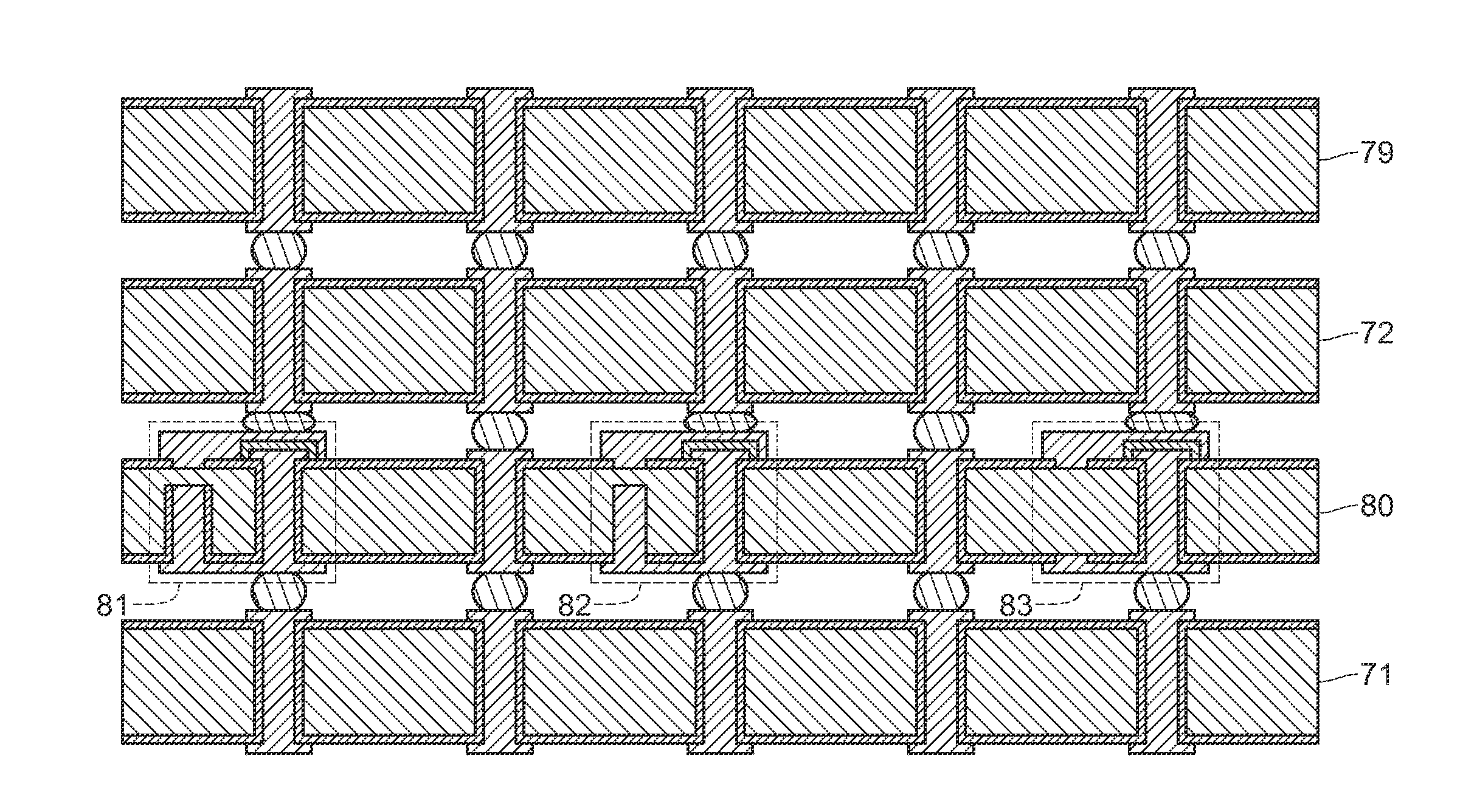
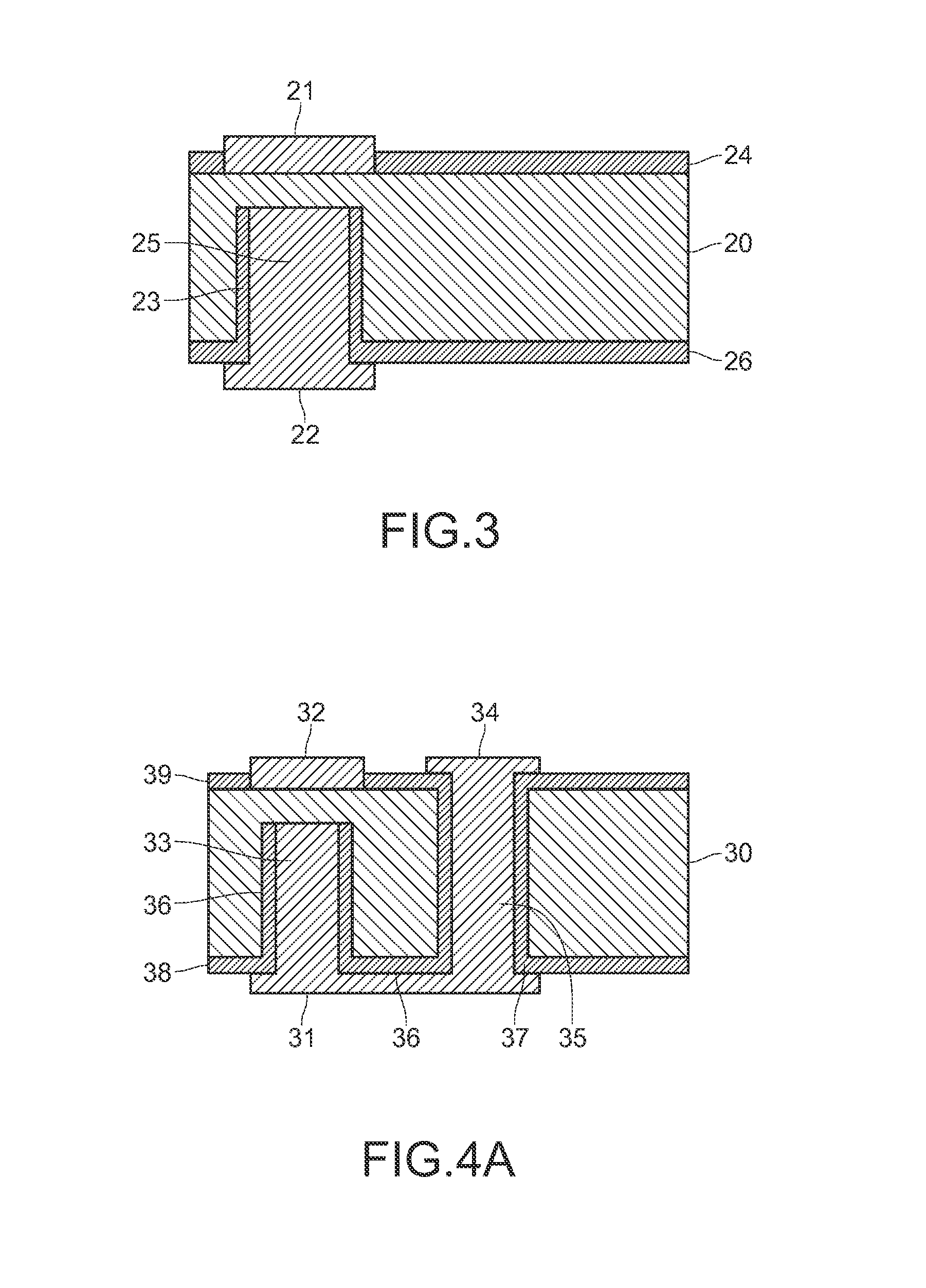
  • Semiconductor substrate assembly
  • Semiconductor substrate assembly
  • Semiconductor substrate assembly

Examples


Embodiment Construction

[0024]The detailed features and advantages of the disclosure are described below in great detail through the following embodiments, the content of which is sufficient for those of ordinary skill in the art to understand the technical content of the disclosure and to implement the disclosure accordingly. Based upon the content of the specification, the claims, and the drawings, those of ordinary skill in the art can easily understand the relevant objectives and advantages of the disclosure.

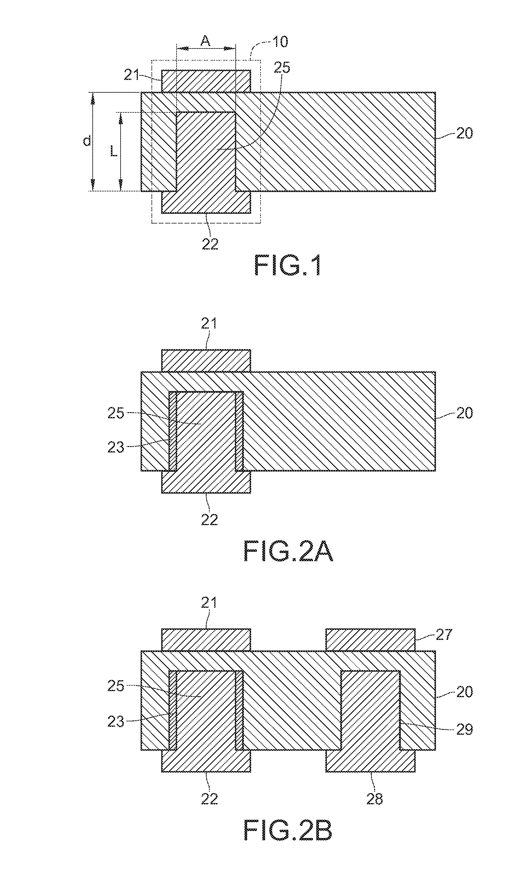
[0025]FIG. 1 illustrates a schematic diagram of a semiconductor substrate assembly according to one embodiment of the disclosure. The semiconductor substrate assembly includes a substrate 20. In one embodiment, the substrate 20 may be a silicon substrate. In one embodiment, the silicon substrate is a chip semiconductor, a silicon semiconductor, or a silicon semiconductor interposer.

[0026]A first conductive pad 21 is formed at a predetermined location of a first surface of the substrate 20. A second...


PUM

PropertyMeasurementUnit
distanceaaaaaaaaaa
distanceaaaaaaaaaa
semiconductoraaaaaaaaaa

Abstract

A semiconductor substrate assembly is proposed. The semiconductor interposer comprises a substrate having a first surface and a second surface opposite to the first surface, a first conductive pad, a second conductive pad and a conductive pillar. The first conductive pad is formed at a predetermined location of the first surface of the substrate. The second conductive pad is formed at a predetermined location of the second surface of the substrate as compared with the position of the first conductive pad. The conductive pillar is formed in the substrate and contacts with one of the first conductive pad and the second conductive pad.

Description

CROSS-REFERENCE STATEMENT[0001]This non-provisional application claims priority under 35 U.S.C. §119(a) on Patent Application No(s). 101129625 filed in Taiwan, R.O.C. on Aug. 15, 2012, the entire contents of which are hereby incorporated by reference.BACKGROUND[0002]1. Technical Field[0003]The disclosure relates to a semiconductor substrate assembly.[0004]2. Related Art[0005]To fulfill the high density package and to improve the channel bandwidth of the high speed integrated circuit system, a through-silicon via (TSV) is a key point in the three dimension integrated circuit (3D ICs) technique. In the integrated circuit technique of the 3D ICs, the TSV package technique is a main central technique and is available to connect a chip to one another vertically. This may reduce the length of connection lines greatly. Moreover, a silicon semiconductor interposer technique is also required in the outside connection of the 3D ICs, provides two dimension connection line layers, and provides ...

Claims


Application Information

Patent Timeline
Patent Type & Authority Applications(United States)
IPC IPC(8): H01L23/48
CPCH01L23/48H01L23/481H01L23/64H01L23/66H01L25/0657H01L2225/06513H01L2225/06541H01L2224/0401H01L2224/05009H01L2224/06181H01L2224/13111H01L2224/16145H01L2224/16146H01L2224/16225H01L2224/16235H01L2224/81192H01L23/49827H01L23/5223H01L21/02107H01L23/147H01L23/5228H01L2924/0002H01L2924/00
Inventor CHEN, PENG-SHULEE, MIN-LINWU, SHIH-HSIENLIU, SHUR-FEN
Owner IND TECH RES INST
Learn More