Electrophysiology catheter design

a catheter design and electrophysiology technology, applied in the field of electrophysiology catheter design, can solve the problems of inability to accurately and reliably detect the map signal of the cardiac electrophysiology catheter, the electrode is more likely to incur local overheating, and the current known cardiac electrophysiology catheters do not accurately and reliably detect the map signal, etc., to achieve the improvement of mapping and/or ablation of the target tissue region, enhance local small area contact pressure, and reduce manufacturing cost and complexity

Active Publication Date: 2014-02-20
MEDTRONIC ABLATION FRONTIERS
View PDF4 Cites 21 Cited by
  • Summary
  • Abstract
  • Description
  • Claims
  • Application Information

AI Technical Summary

Benefits of technology

[0010]The present invention relates to a method, device, and system for improved mapping and / or ablation of a target tissue region, while reducing manufacturing cost and complexity. In a first embodiment, the device may generally include an elongate body and a distal assembly affixed to the elongate body and including a treatment electrode having a first surface, a conductive mapping region, and a selectively conductive ablation region. The selectively conductive ablation region may be conductive of high-frequency current and substantially non-conductive of low-frequency current. The treatment electrode may be composed of metal, such as platinum, platinum alloys, gold, gold alloys, gold with a coating of tantalum, copper with a coating of tantalum, aluminum, tungsten, titanium, tantalum, hafnium, niobium, silver, zirconium, and combinations thereof. The selectively conductive ablative region may include an oxide layer on the treatment electrode first surface. For example, the treatment electrode may be composed of gold and the selectively conductive ablative region may include a layer of oxidized tantalum. Further, the selectively conductive ablative region may be larger than the conductive mapping region. In another embodiment, the treatment electrode may include a coiled region that is prominent from the elongate body, for example, treatment electrode may be a coiled hypotube electrode. The perimeter of the hyptotube electrode may include one or more substantially angular bends and / or one or more protuberances to further enhance local small area contact pressure with tissue. In another embodiment, the device may include two treatment electrodes, each treatment electrode being substantially disposed about a circumference of the elongate body, the conductive mapping regions of the treatment electrode being coaxial with the longitudinal axis of the elongate body, and the conductive mapping region of each treatment electrode being distal of the selectively conductive ablation region of each electrode. In another embodiment, the elongate body of the device may define a distal region, and the device may further comprise two or more treatment electrodes, each treatment electrode being substantially disposed within a discrete circular sector of the distal tip.

Problems solved by technology

For example, motion artifacts caused by a beating heart and nonuniform ventricular contraction can significantly distort detected MAP signals, as movement of the heart will vary the pressure of (and therefore alter the contact between) the mapping electrodes on the heart tissue as well as resulting in unstable sliding contact of the electrodes.
Currently known diagnostic cardiac electrophysiology catheters do not accurately and reliably detect MAP signals.
When smaller electrodes, and therefore a smaller active surface area, are used, the electrodes are more likely to incur local overheating, which can lead to thermal denaturation of blood proteins, producing adherent or embolic coagulum or other undesirable effects downstream of the electrodes and the treatment site.

Method used


Image

  • Electrophysiology catheter design
  • Electrophysiology catheter design
  • Electrophysiology catheter design

Examples


first embodiment

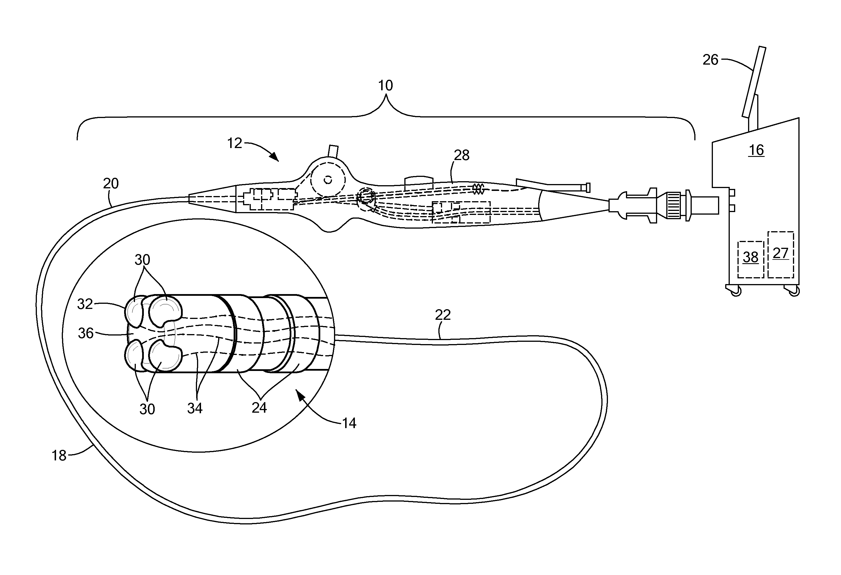
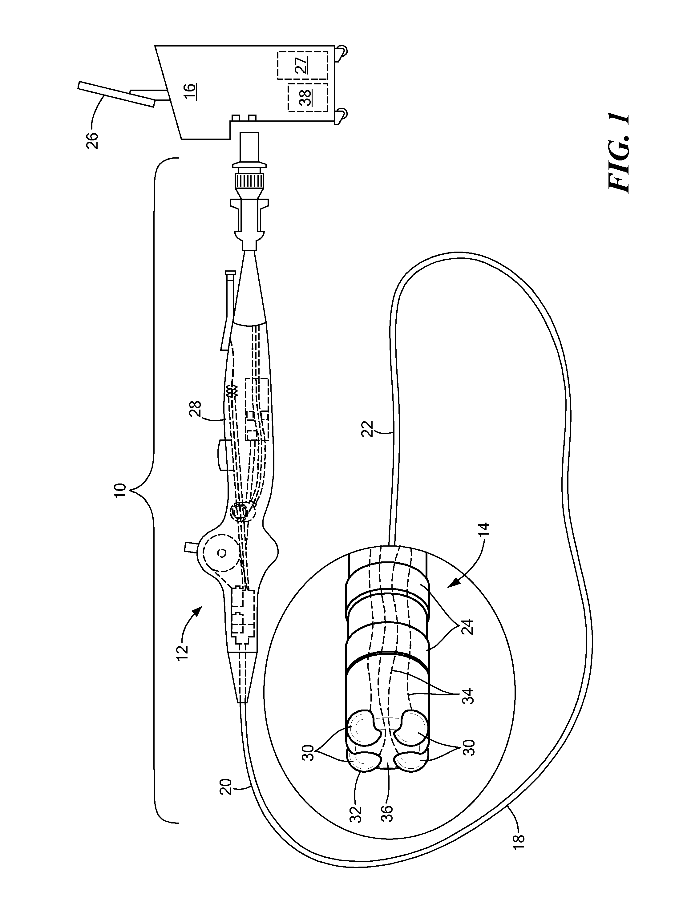
[0038]Referring now to FIG. 2, a distal assembly 14 is shown. The distal assembly 14 may include a housing 36 and one or more electrodes 30, such as mono-phasic action potential (MAP) electrodes, each positioned a radial distance from the longitudinal axis 40 of the housing 36. If two electrodes 30 are used, the electrodes 30 may be positioned opposite each other. If three or more electrodes 30 are used (for example, four electrodes are shown in FIG. 2), the electrodes 30 may have a radial symmetry about the housing longitudinal axis 40.

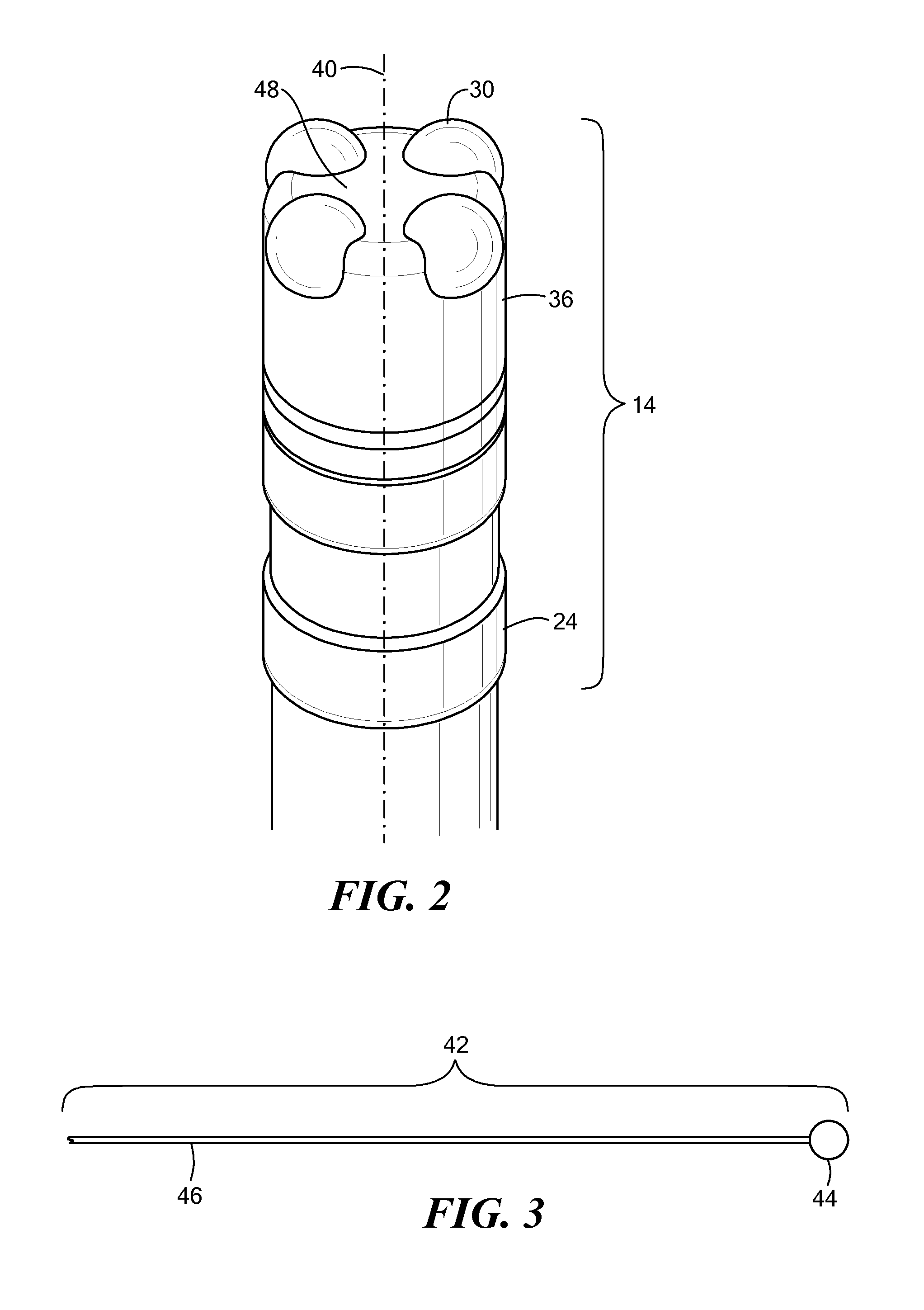
[0039]The distal assembly 14 shown in FIG. 2 may have been formed according to the method shown and described in FIGS. 3-5. For example, one or more bulbed wires 42 comprising a bulb portion 44 and a wire portion 46 may be created (as shown and described in FIG. 3). The wire 46 portion of each bulbed wire 42 may then be anodized (as shown and described in FIG. 4), and the bulb portion 44 of each bulbed wire 42 may be composed of the non-anodized mate...

third embodiment

[0046]Referring now to FIGS. 6A and 6B, a second and third embodiment of a distal assembly 14 is shown. In both embodiments, the electrode head 32 (the conductive portion) and the electrode wire 34 (the insulated portion) are not only composed of the same material, but are also created from a single piece of material (collectively referred to as an “electrode”). This may reduce manufacturing cost and complexity. Additionally, more than one electrode wires 34 may be used within a catheter body 18 without the need for including insulation material between the wires.

[0047]In the embodiment shown in FIG. 6A, a plurality (for example, three) electrode wires 34 are disposed within a medical device, such as a catheter elongate body 18. Each wire 34 may be composed of a metal (for example, tantalum or TaKS) and include an outer insulative oxide layer (for example, tantalum pentoxide). When low-frequency or DC voltage flows through the wire, the wire 34 will function as an insulated conducto...

fifth embodiment

[0049]Referring now to FIGS. 7A and 7B, a fourth and fifth embodiment of the distal assembly 14 are shown. These embodiments include an electrode 30 that has both mapping and ablation functionality. As shown in FIG. 7A, one or more electrodes 30 may be disposed about the distal portion 22 of a medical device, such as the flexible, elongate body 18 of a catheter. Although FIG. 7A shows two electrodes 30, any number of electrodes 30 may be used. Each electrode 30 may include a conductive region 70 and a region that is selectively conductive 72. As described herein, the electrode 30 may be composed of a highly conductive metal such as gold and may include a thin film coating of a metal such as tantalum, and the selectively conductive region 72 may include an outer oxide layer, whereas the conductive region 70 does not. The oxide layer may be an oxide of aluminum, tungsten, titanium, tantalum, hafnium, niobium, zirconium (and alloys thereof). The oxide layer in the case of tantalum pent...


PUM

PropertyMeasurementUnit
melting pointaaaaaaaaaa
thickaaaaaaaaaa
diameteraaaaaaaaaa

Abstract

The present invention relates to a method, device, and system for improved mapping and / or ablation of a tissue. The device may generally include an elongate body and a distal assembly affixed to the elongate body that includes a treatment electrode having a conductive mapping region and a selectively conductive ablation region that is conductive of high-frequency current and substantially non-conductive of low-frequency current. Alternatively, the device may generally include a treatment electrode having a conductive mapping or ablation region and a region that is coated with an electrically insulated but thermally conductive layer.

Description

CROSS-REFERENCE TO RELATED APPLICATION[0001]This application is related to and claims priority to U.S. Provisional Patent Application Ser. No. 61 / 684,385, filed Aug. 17, 2012, entitled MONOPHASIC ACTION POTENTIAL CATHETER DESIGN, and is related to and claims priority to U.S. Provisional Patent Application Ser. No. 61 / 727,163, filed Nov. 16, 2012, entitled MONO-PHASIC ACTION POTENTIAL ELECTROGRAM CATHETER, the entirety of both of which is incorporated herein by reference.STATEMENT REGARDING FEDERALLY SPONSORED RESEARCH OR DEVELOPMENT[0002]n / aFIELD OF THE INVENTION[0003]The present invention relates to a device and system for improved mapping and tissue ablation that may be manufactured at a reduced cost and complexity.BACKGROUND OF THE INVENTION[0004]Medical procedures are available for treatment of a variety of cardiovascular conditions, such as cardiac arrhythmias, atrial fibrillation, and other irregularities in the transmission of electrical impulses through the heart. As an alte...

Claims


Application Information

Patent Timeline
Patent Type & Authority Applications(United States)
IPC IPC(8): A61B18/14A61B18/18
CPCA61B18/18A61B18/14A61B2018/00071A61B2018/00107A61B2018/00351A61B2018/00839A61B2018/1467A61B2018/147A61B2018/1497A61B2018/00029A61B2018/0016A61B2018/1407A61B2018/1435Y10T29/49176A61B18/1492Y10T29/49172H01R43/24H05K13/00A61B5/283A61B5/287A61B5/297A61B2018/00083A61B2018/00095A61B2018/00577A61B2018/00642A61L29/02H05K9/00
Inventor STEWART, MARK T.BENSCOTER, MARK ALLENEVANS, JON VIRGILLASKE, TIMOTHY G.MARTINEZ, GONZALO
Owner MEDTRONIC ABLATION FRONTIERS
Why Eureka
Try Eureka