Battery state estimation system, battery control system, battery system, and battery state estimation method

a battery state estimation and control system technology, applied in the field of battery state estimation system, battery control system, battery system, etc., can solve the problems of unstable operation results, deterioration of the accuracy of calculation of the charge characteristic determined from the battery voltage, and difficulty in coping with a charge change, etc., to achieve satisfactory accuracy

Active Publication Date: 2014-02-27
HITACHI VEHICLE ENERGY
View PDF16 Cites 27 Cited by
  • Summary
  • Abstract
  • Description
  • Claims
  • Application Information

AI Technical Summary

Benefits of technology

[0010]According to the battery state estimation system of the present invention, a state of charge of a battery can be estimated with satisfactory accuracy even when a battery temperature is low and a battery current is small.

Problems solved by technology

The technology described in JP-2011-85592-A encounters a difficulty in coping with a change in the charge characteristic due to a change in temperature because the current of the storing device and its internal resistance cause the weight to change.
For example, when a battery temperature is low, the internal resistance may greatly change depending on a battery current, and therefore the accuracy of calculation of the charge characteristic determined from the battery voltage is apt to deteriorate.
Particularly when the battery temperature is low and the battery current is small, there is a noticeable tendency that an operational result becomes unstable.

Method used


Image

  • Battery state estimation system, battery control system, battery system, and battery state estimation method
  • Battery state estimation system, battery control system, battery system, and battery state estimation method
  • Battery state estimation system, battery control system, battery system, and battery state estimation method

Examples


first embodiment

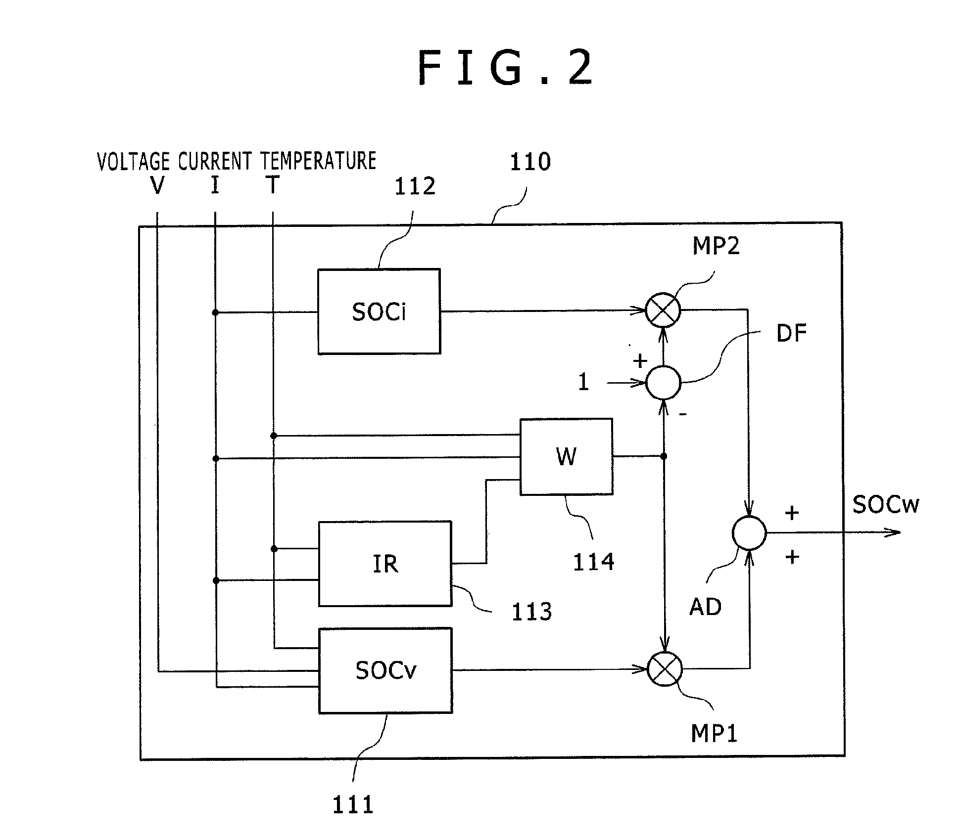
[0044]In the battery state estimation system 110 according to the first embodiment as described above, when the battery temperature T is lower than the predetermined threshold value, and the battery current I is smaller than the predetermined threshold value, the weight W is corrected in such a manner that the specific gravity at SOCi becomes large. It is thus possible to minimize the influence of error expansion due to the internal resistance R, which is difficult to predict under conditions of the low temperature and the small current and estimate SOC with satisfactory accuracy.

second embodiment

[0045]Although the first embodiment has described that the coefficient Wgain is defined according to the association table shown in FIG. 6, the value of Wgain corresponding to the battery temperature T or the battery current I undefined in the association table can be determined by performing interpolation operations such as linear interpolation, etc. by the weight computing unit 114.

[0046]For example, when the battery temperature T=5° C. and the battery current I=0 A, the coefficient Wgain can be set to Wgain=25.5 by taking the middle between Wgain=50 at T=0° C. and Wgain=1 at T=10° C. Likewise, when the battery temperature T=−40° C. and the battery current I=5 A, the coefficient Wgain can be set to 50.5 by taking the middle between Wgain=1 at I=−10 A and Wgain=100 at I=0 A.


PUM


Abstract

A battery state estimation system estimates a state of charge of a chargeable battery. A SOCv computing unit calculates a state of charge of the battery using a voltage applied across the battery. A SOCi computing unit integrates a current flowing through the battery to calculate a state of charge of the battery. A SOCw computing unit which performs weighted addition to the state of charge of the battery calculated by the SOCv computing unit and the state of charge of the battery calculated by the SOCi computing unit, wherein when the temperature of the battery is a threshold value or less and the current flowing through the battery is a threshold value or less, the SOCw computing unit sets the specific gravity at the state of charge of the battery calculated by the SOCi computing unit larger than that in other cases upon the weighted addition.

Description

BACKGROUND OF THE INVENTION[0001]1. Field of the Invention[0002]The present invention relates to a technology which estimates a state of charge of a battery.[0003]2. Description of the Related Art[0004]In devices each using storing devices such as a lithium secondary battery, a nickel-metal hydride battery, a lead battery, an electric double-layer capacitor, etc., e.g., a battery system, a distributed power storage system and an electric vehicle, a state detection device for detecting the state of the storing device has been employed to use the storing device with safety and effectively. As the state of the storing device, there are mentioned a state of charge (SOC) indicative of the extent to which it is being charged, or how dischargeable amount of charge remains, a state of health (SOH) indicative of how it is deteriorated, etc.[0005]An SOC for a portable device and in a battery system of an electric vehicle or the like can be detected by integrating a discharge current from full...

Claims


Application Information

Patent Timeline
Patent Type & Authority Applications(United States)
IPC IPC(8): H02J7/00
CPCH02J7/00G01R31/367G01R31/3842G01R31/374G01R31/389G01R31/3828
Inventor IGARASHI, NAOYUKIOHKAWA, KEIICHIRO
Owner HITACHI VEHICLE ENERGY
Why Eureka
Try Eureka