Gate driver circuit and display apparatus having the same

a driver circuit and display device technology, applied in electronic switching, pulse technique, instruments, etc., can solve the problems of insufficient darkness for a black image, pixel tft may not stay in the off state completely, etc., to prolong the period of control signal, reduce ripple in control signal, and slow down the effect of threshold voltage shifting

Active Publication Date: 2014-02-27
INNOLUX CORP
View PDF3 Cites 13 Cited by
  • Summary
  • Abstract
  • Description
  • Claims
  • Application Information

AI Technical Summary

Benefits of technology

[0010]This disclosure is to reduce the frequency of the control signal in the pull-down TFT of a GOA output circuit, so as to extend the control signal's period. Thereby, the ripple in the control signal can be diminished, the shifting of its threshold voltage can be slowed down, and thus the performance and reliability of the gate driver circuit and the display apparatus can be improved.

Problems solved by technology

However, the pixel TFT may not stay in the OFF state completely due to a leakage current Ioff flowing from Vpixel to Vdata, because the ripple voltage may still bias the gate of the pixel TFT.
A positive ripple with a large peak voltage may cause a leakage current flowing in the pixel TFT to lower the pixel voltage Vpixel, rendering insufficient darkness for a black image.

Method used


Image

  • Gate driver circuit and display apparatus having the same
  • Gate driver circuit and display apparatus having the same
  • Gate driver circuit and display apparatus having the same

Examples


Embodiment Construction

[0032]For further understanding and recognizing the fulfilled functions and structural characteristics of the disclosure, several exemplary embodiments cooperating with detailed description are presented as the following. Reference will now be made in detail to the preferred embodiments, examples of which are illustrated in the accompanying drawings. Although the terms “first”, “second” and “third” are used to describe various elements, these elements should not be limited by the term. Also, unless otherwise defined, all terms are intended to have the same meaning as commonly understood by one of ordinary skill in the art.

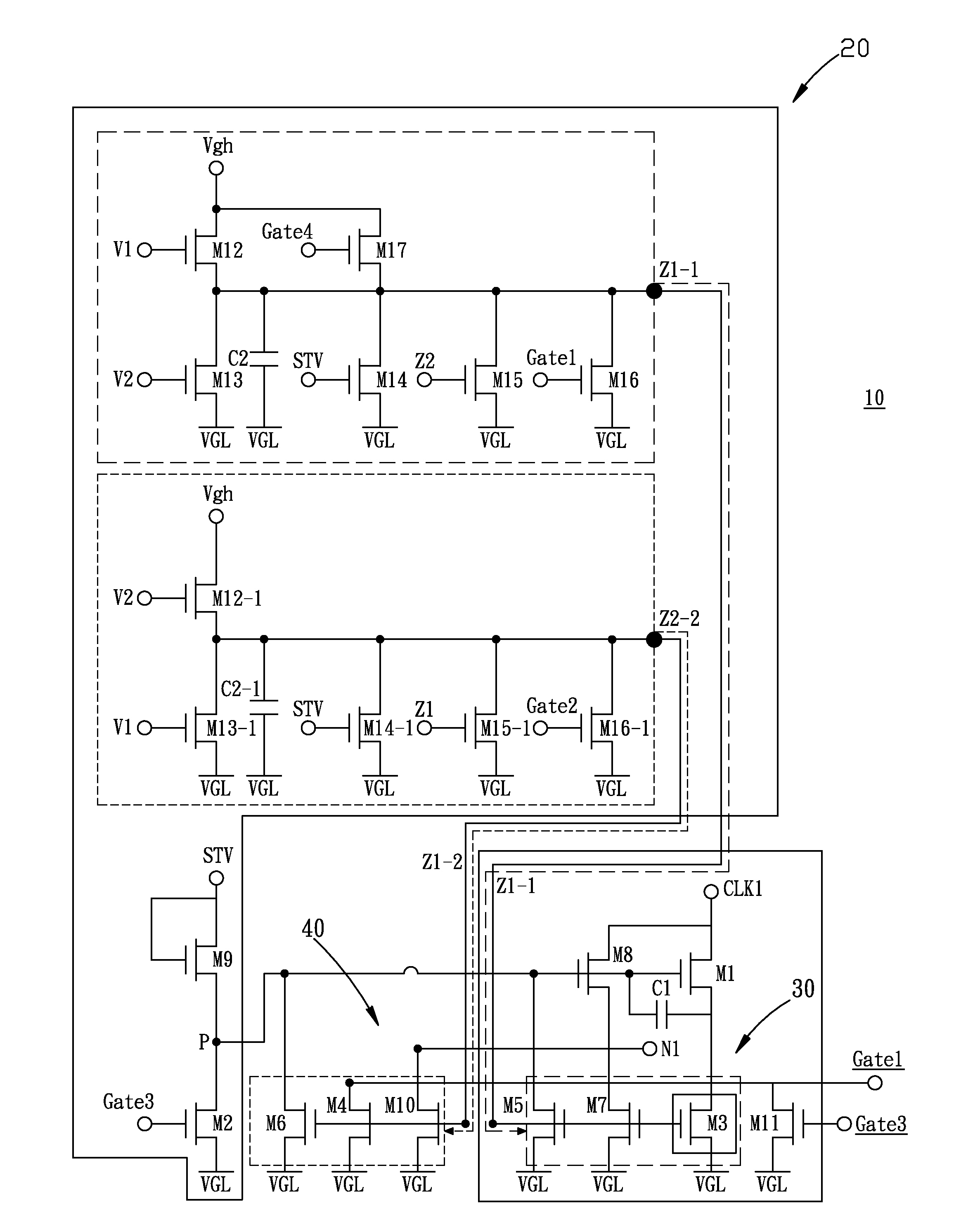
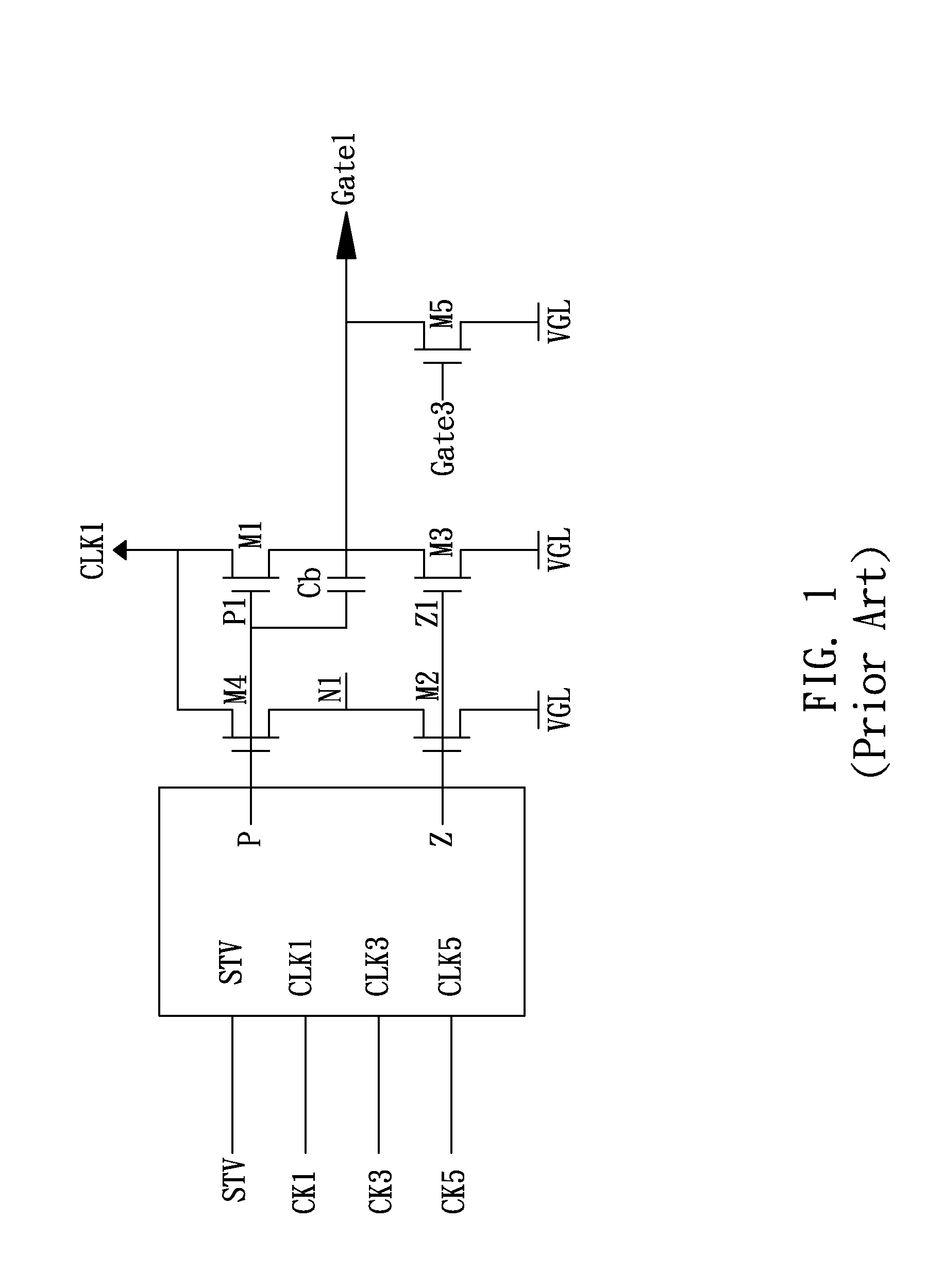
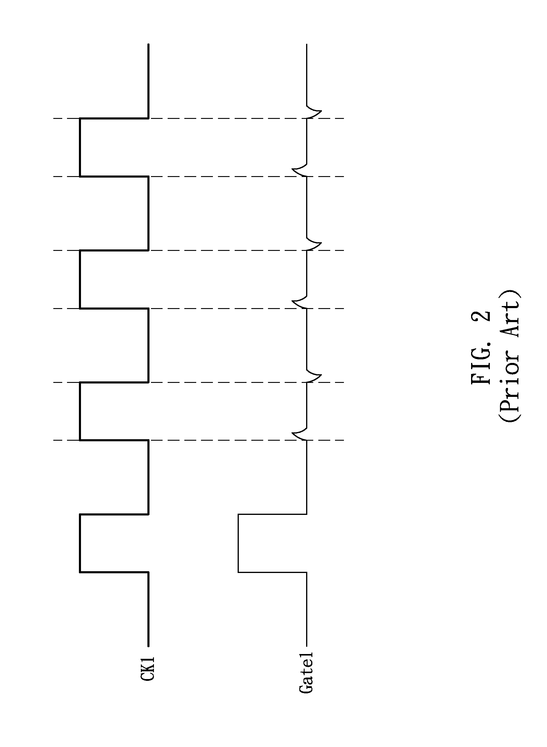
[0033]FIG. 7 schematically shows a block diagram of a gate driver circuit 100 with multiple output stages according to an embodiment of this disclosure. FIG. 8 shows a circuit diagram illustrating the gate driver circuit 100 in the embodiment. FIG. 9 shows a control signal configured for controlling a pull-down TFT in the embodiment, in comparison with that in the ...


PUM


Abstract

This disclosure provides a gate driver circuit in a display. The gate driver circuit includes shift registers configured for receiving clock and start signals and generating a gate signal to drive a row of the pixels, arranged at intersections of the gate lines and the data lines on a panel, each register comprising: a control unit having a clock input, a first voltage input, a second voltage input, and a first output; and a first output unit having a first pull-down TFT electrically connected to one of the first outputs and a gate-driving terminal configured for providing the gate signal; wherein one of the clock signals at the clock input is provided to the first output unit; and a first control signal's period at the first output is longer than the clock signal's period at the clock input and shorter than the period of a frame.

Description

[0001]This application claims the benefit of Taiwan application Serial No. 101130268, filed Aug. 21, 2012, the disclosure of which is incorporated by reference herein in its entirety.TECHNICAL FIELD[0002]The present disclosure relates to the field of driver circuit, and more particularly, to a gate driver circuit and a display apparatus with the gate driver circuit.TECHNICAL BACKGROUND[0003]A driver circuit is a key component in a liquid-crystal display (LCD). Conventionally, the driver circuit was fabricated in the form of integrated circuit (IC) to drive an LCD panel. Further, to reduce the fabrication cost and improve the device performance, an amorphous-silicon integrated gate driver, hereafter “ASG”, has been developed, in which the gate driver is integrated into the LCD panel in the array process of the amorphous-silicon-based display manufacturing. This scheme is also referred to as the gate driver on array (GOA) or the gate driver on panel (GOP).[0004]FIG. 1 schematically sh...

Claims


Application Information

Patent Timeline
Patent Type & Authority Applications(United States)
IPC IPC(8): H03K17/16G09G3/36
CPCG09G3/3696H03K17/162G09G3/3677G09G2310/0286G09G2320/02G09G2320/0238G11C19/287
Inventor HSU, WEN-TSAICHIANG, CHIEN-HSUEH
Owner INNOLUX CORP
Why Eureka
Try Eureka