

Shovel and method of controlling shovel
a shovel and shovel technology, applied in the field of shovels, can solve problems such as sudden increase of hydraulic load
- Summary
- Abstract
- Description
- Claims
- Application Information
AI Technical Summary
Benefits of technology
Problems solved by technology
Method used
Image

Examples
first embodiment
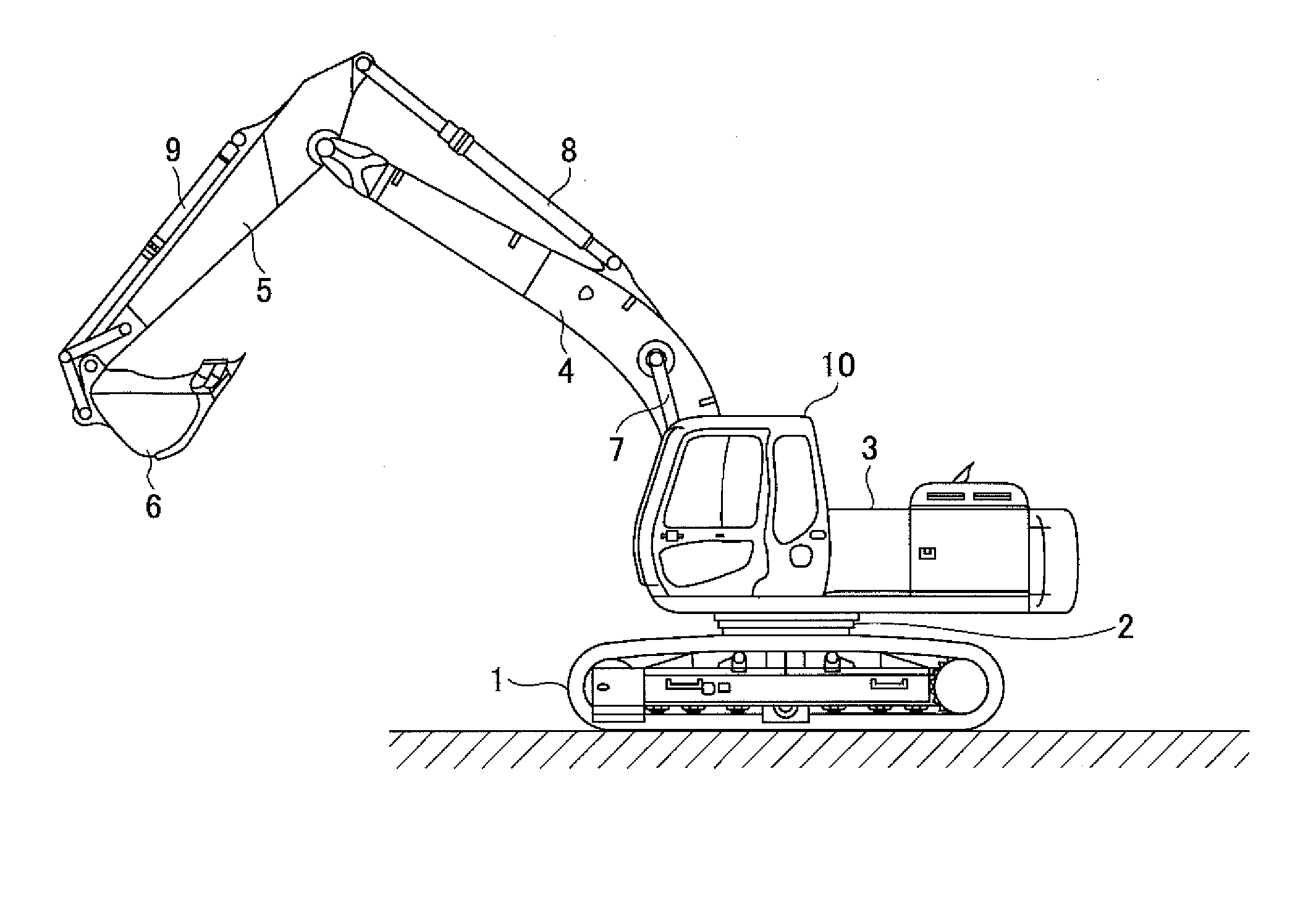
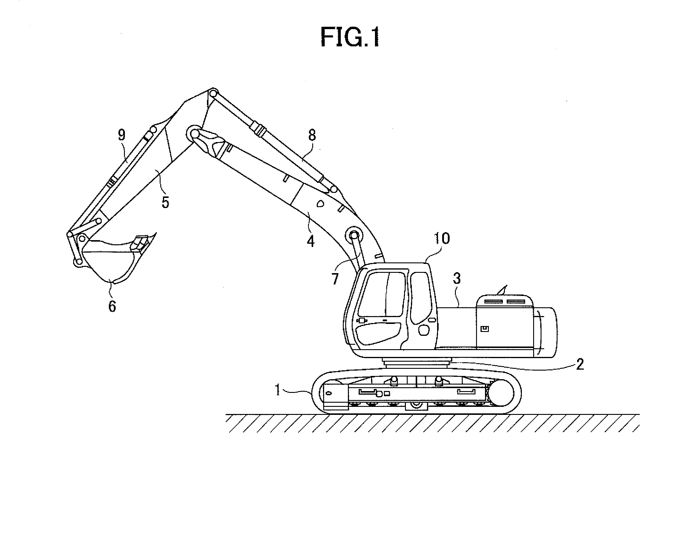
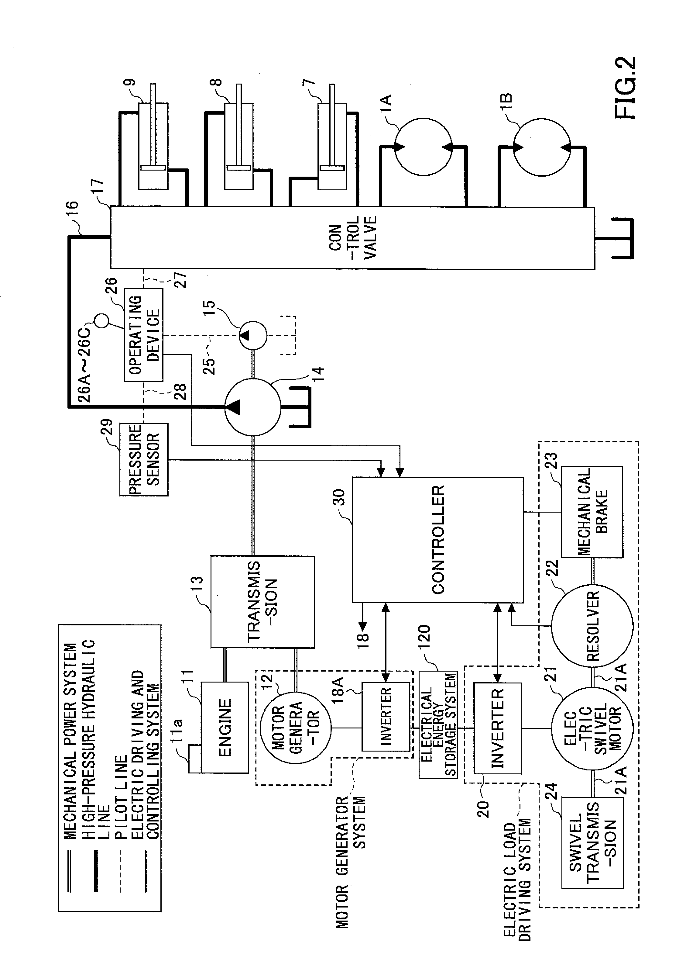
[0047]Within the first embodiment, a relay 130-1 is provided as a shutoff switch for shutting off a power supply line 114, which connects the positive terminal of the capacitor 19 to the electric power connection terminal 104 of the buck-boost converter 100. The relay 130-1 is arranged between the positive terminal of the capacitor 19 and a connection point 115 of the capacitor voltage detecting portion 112, which is connected to the power supply line 114. The relay 130-1 is operated by a signal from the controller 30. By shutting off the power supply line 114 extending from the capacitor 19, the capacitor 19 can be disconnected from the buck-boost converter 100.
[0048]Further, a relay 130-2 is provided as a shutoff switch for shutting off a power supply line 117, which connects the negative terminal of the capacitor 19 to the electric power connection terminal 104 of the buck-boost converter 100. The relay 130-2 is arranged between the negative terminal of the capacitor 19 and a con...
second embodiment
[0086]Next, an engine control of the present invention is described.
[0087]FIG. 5 is a time chart illustrating changes of various control elements in a case where the engine control of the second embodiment of the present invention is performed. Referring to FIG. 5, a solid line represents changes of the control elements in a case where the engine control of this embodiment is performed, and a dot chain line represents changes of the control elements in a case where the engine control of this embodiment is not performed. The changes (the dot chain line) of the control elements in the case where the engine control of this embodiment is not performed are illustrated to compare with the changes of the control elements in the case where the engine control of this embodiment is performed.
[0088]Referring to FIG. 5, (a) illustrates a change of an operation quantity of the operating lever (the arm operating lever), (b) illustrates a change of an output (electrically generated power) from the...
PUM
 Abstract
Description
Claims
Application Information