Plugged honeycomb structure

a honeycomb structure and plugged technology, applied in the field can solve the problems of easy cracks over the whole honeycomb structure body, disadvantageous low isostatic strength of honeycomb structure body of hexagonal cells, etc., to enhance the isostatic strength of plugged honeycomb structure, and less influence on pressure loss

Active Publication Date: 2014-03-06
NGK INSULATORS LTD
View PDF13 Cites 14 Cited by
  • Summary
  • Abstract
  • Description
  • Claims
  • Application Information

AI Technical Summary

Benefits of technology

[0028]A plugged honeycomb structure of the present invention includes a honeycomb structure body, outflow side plugged portions, and inflow side plugged portions, and a cell shape in a cross section perpendicular to a cell extending direction is a hexagonal shape. In the plugged honeycomb structure of the present invention, six corner portions of each of the hexagonal cells include “specific corner portions” and “unspecific corner portions” as described below. Moreover, in the plugged honeycomb structure of the present invention, at least one of the specific corner portions is provided with a reinforcing portion so that a shape of the specific corner portion is rounded. That is, the at least one specific corner portion is provided with the above reinforcing portion, and the unspecific corner portions are not provided with the above reinforcing portions. “The specific corner portion” is a corner portion between two sides which are two partition walls constituting the corner portion and at least one of which is the partition wall separating the inflow cells or the outflow cells from each other. “The unspecific corner portion” is a corner portion between two sides which are two partition walls constituting the corner portion and each of which is the partition wall separating the inflow cell and the outflow cell.
[0029]In the plugged honeycomb structure of the hexagonal cells, from relations in shape and arrangement between the cells, “the specific corner portions” and “the unspecific corner portions” are present as described above. Here, in the plugged honeycomb structure, a fluid (an exhaust gas) which has flowed into the inflow cells from an inflow side end surface permeates the partition walls each separating the inflow cell and the outflow cell, moves to the outflow cells, and is discharged as a purified gas from an outflow side end surface. That is, in the plugged honeycomb structure of the hexagonal cells, the movement (the permeation) of the fluid through the partition walls is mainly performed through the partition walls each separating the inflow cell and the outflow cell. Therefore, the movement of the fluid through the partition walls each separating the inflow cell and the outflow cell has a large influence on a pressure loss of the plugged honeycomb structure. In particular, when the exhaust gas which has flowed into the cells from the inflow side end surface is discharged as the purified gas from the outflow side end surface, the movement of the exhaust gas through the partition walls each separating the inflow cell and the outflow cell is essentially required. On the other hand, in the partition walls each separating the inflow cells or the outflow cells from each other, a differential pressure between the inflow cells or the outflow cells is hardly generated, and hence the movement (the permeation) of the fluid through the partition walls is scarcely performed. Therefore, it can be considered that the movement of the fluid through the partition walls each separating the inflow cells or the outflow cells from each other has remarkably little influence on the pressure loss, as compared with the movement of the fluid through the partition walls each separating the inflow cell and the outflow cell.
[0030]In the plugged honeycomb structure of the present invention, the at least one specific corner portion is provided with the reinforcing portion so that the shape of the specific corner portion is rounded, which can enhance an isostatic strength of the plugged honeycomb structure. Furthermore, at least one of the two partition walls constituting this specific corner portion is “the partition wall separating the inflow cells or the outflow cells from each other” which has a less influence on the pressure loss. Therefore, even when this specific corner portion is provided with the reinforcing portion, it is possible to suppress an increase in pressure loss and a decrease in capacity of deposited ash, as compared with a case where the unspecific corner portions are provided with the reinforcing portions.

Problems solved by technology

However, a honeycomb structure body of hexagonal cells disadvantageously has a low isostatic strength, as compared with a honeycomb structure body of cells having a quadrangular sectional shape in a cell extending direction.
Moreover, when cracks are generated in a part (one portion) of the honeycomb structure body of the hexagonal cells, the honeycomb structure body has the problem that the cracks easily extend over the whole honeycomb structure body.
Therefore, when the round portions are arranged in corner portions of all cells, a pressure loss increases, and a capacity of deposited ash decreases in a plugged honeycomb structure.
It is difficult to purify the ash by a catalyst or the like.

Method used


Image

  • Plugged honeycomb structure
  • Plugged honeycomb structure
  • Plugged honeycomb structure

Examples


example 1

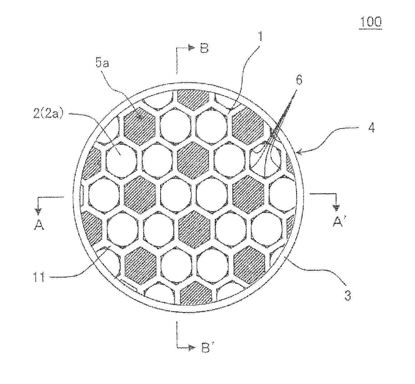
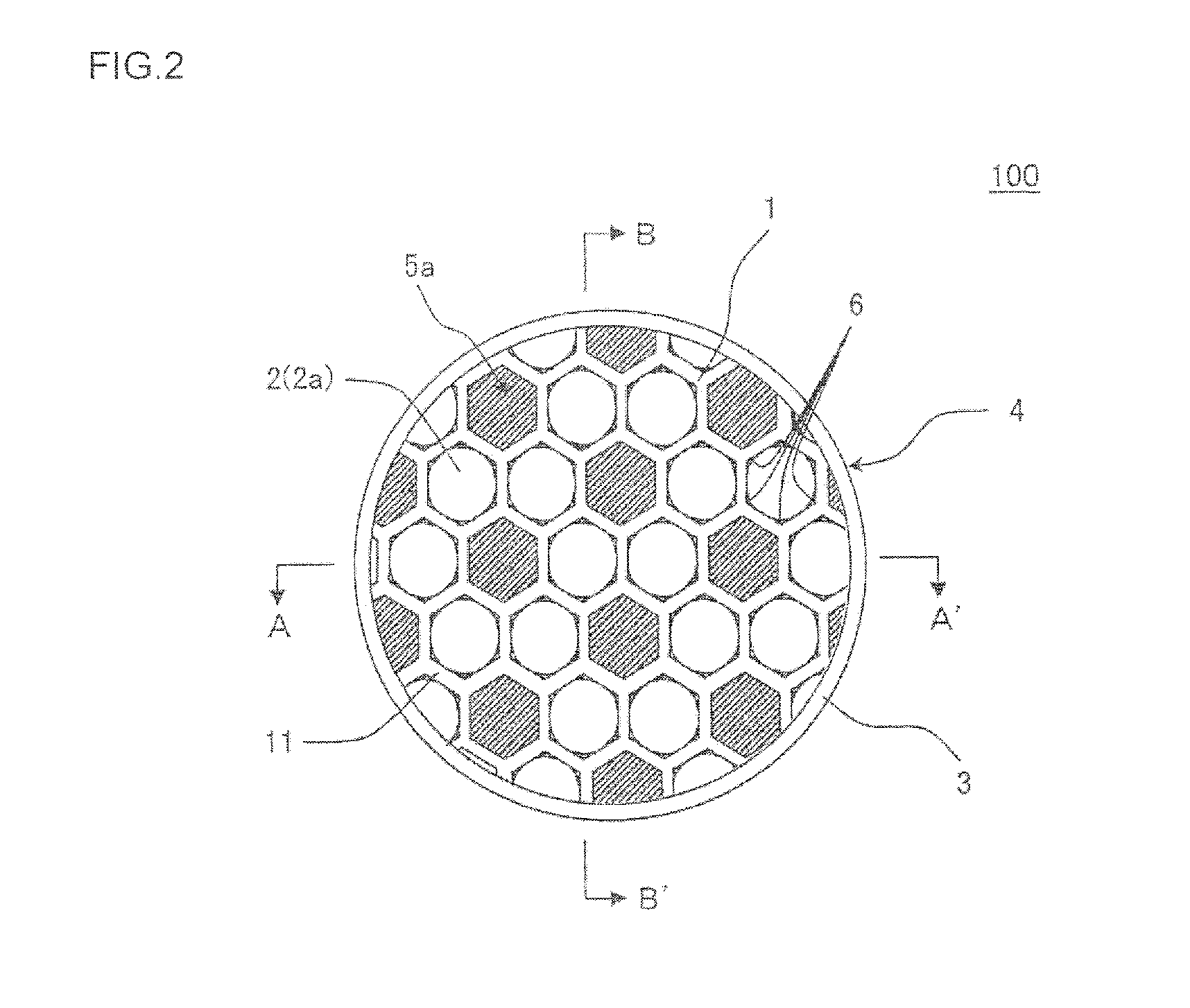
[0113]As a ceramic raw material, a cordierite forming raw material (alumina, talc and kaolin) was used. A mass ratio of alumina, talc and kaolin was a mass ratio at which cordierite was obtained after firing. The ceramic raw material was mixed with a binder (methylcellulose) and water, to obtain a ceramic forming raw material. The obtained ceramic forming raw material was kneaded by using a kneader to obtain a kneaded material.

[0114]Next, the obtained kneaded material was formed by using a vacuum extrusion forming machine, to obtain a formed honeycomb body including partition walls with which hexagonal cells were formed. For the hexagonal cells, as in a plugged honeycomb structure 100 shown in FIG. 1, FIG. 2, FIG. 3A, FIG. 3B, and FIG. 4A to FIG. 4C, all hexagonal cells 2 had the same shape. In this formed honeycomb body, all corner portions to become specific corner portions were provided with reinforcing portions 6 at formation. This is indicated as “all the specific corner portio...

examples 2 to 10

[0135]The procedures of Example 1 were repeated except that “an area ratio (%) covered by reinforcing portions” and “arrangement of the reinforcing portions” were changed as shown in Table 1, to manufacture plugged honeycomb structures. The obtained plugged honeycomb structures were subjected to evaluation of “an isostatic strength”, “an initial pressure loss”, “a capacity of deposited ash”, and “a pressure loss at the ash deposition”. The evaluation results are shown in Table 1. Additionally, in Example 2, specific corner portions corresponding to 80% of the specific corner portions of hexagonal cells were provided with reinforcing portions. In Example 3, specific corner portions corresponding to 50% of the specific corner portions of hexagonal cells were provided with reinforcing portions. In Example 3, when the specific corner portions were adjacently arranged to share one side constituting each of the hexagonal cells, the specific corner portions were provided with the reinforci...

example 11

[0141]The procedures of Example 1 were repeated except that a hexagonal cell shape was formed as in a plugged honeycomb structure 200 shown in FIG. 6, FIG. 7A and FIG. 7E, to manufacture a plugged honeycomb structure. The obtained plugged honeycomb structure was subjected to evaluation of “isostatic strength”, “initial pressure loss”, “capacity of deposited ash”, and “pressure loss at the ash deposition”. The evaluation results are shown in Table 2. In the plugged honeycomb structure of Example 11, a shape of outflow cells was a regular hexagonal shape having one side of 0.85 mm. Moreover, in a shape of inflow cells, among six sides of a hexagonal shape, a length of each of three sides adjacent to the outflow cells via partition walls (i.e., long sides) was 0.85 mm, and a length of each of three sides adjacent to the inflow cells via partition walls (i.e., short sides) was 0.50 mm. In the plugged honeycomb structure of Example 11, all corner portions that became specific corner port...


PUM

PropertyMeasurementUnit
thicknessaaaaaaaaaa
thicknessaaaaaaaaaa
thicknessaaaaaaaaaa

Abstract

A plugged honeycomb structure including a honeycomb structure body, outflow side plugged portions, and inflow side plugged portions. A shape of cells in a cross section is a hexagonal shape. Among six corner portions of each of the hexagonal cells, the corner portion between two partition walls at least one of which is the partition wall separating inflow cells or outflow cells from each other is a specific corner portion, and the corner portion between the two partition walls each of which is the partition wall separating the inflow cell and the outflow cell is an unspecific corner portion. At least one of the specific corner portions is provided with a reinforcing portion so that a shape of the specific corner portion is rounded, and the unspecific corner portions are not provided with the reinforcing portions.

Description

[0001]The present application is an application based on JP-2012-196680 filed on Sep. 6, 2012 with the Japanese Patent Office, the entire contents of which are incorporated herein by reference.BACKGROUND OF THE INVENTION[0002]1. Field of the Invention[0003]The present invention relates to a plugged honeycomb structure, and more particularly, it relates to a plugged honeycomb structure capable of enhancing an isostatic strength and suppressing an increase in pressure loss and a decrease in capacity of deposited ash.[0004]2. Background Art[0005]In exhaust gases discharged from an internal combustion engine such as a diesel engine, various burning devices, and the like, a large amount of particulate matter mainly composed of soot is included. Hereinafter, the particulate matter will be abbreviated to the “PM”. When the PM in the exhaust gas is discharged to the atmosphere as it is, an environmental pollution is caused. Therefore, in an exhaust system of the exhaust gas, a diesel partic...

Claims


Application Information

Patent Timeline
Patent Type & Authority Applications(United States)
IPC IPC(8): B01D46/24
CPCB01D46/2429B01D46/247B01D46/2484B01D46/2492
Inventor HIRAKAWA, TOSHIHIROYAMADA, TOSHIOSAKASHITA, SATOSHI
Owner NGK INSULATORS LTD
Why Eureka
Try Eureka