Composite charged particle beam apparatus and thin sample processing method

a technology of charged particles and beam apparatus, applied in electrical apparatus, electrical discharge tubes, decorative arts, etc., can solve problems such as affecting observation, and achieve the effect of reducing streaks

Active Publication Date: 2014-03-06
HITACHI HIGH TECH SCI CORP
View PDF2 Cites 21 Cited by
  • Summary
  • Abstract
  • Description
  • Claims
  • Application Information

AI Technical Summary

Benefits of technology

[0025]According to the illustrative aspects of the present invention, even when a sample having a structure such as a semiconductor device is more thinned, it

Problems solved by technology

Therefore, there is a problem that in an observation image of the observation surface, the streak formed by ion beam processing may appear in a structure in addition to

Method used


Image

  • Composite charged particle beam apparatus and thin sample processing method
  • Composite charged particle beam apparatus and thin sample processing method
  • Composite charged particle beam apparatus and thin sample processing method

Examples


first exemplary embodiment

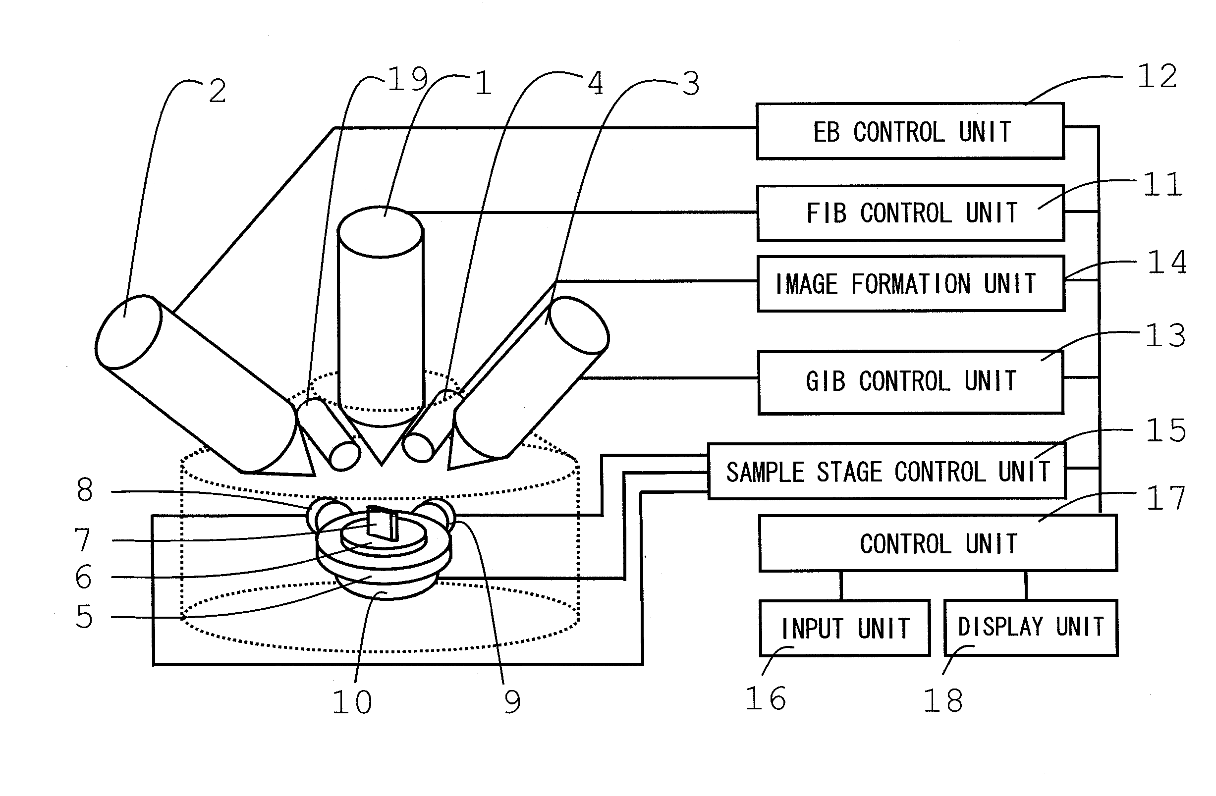
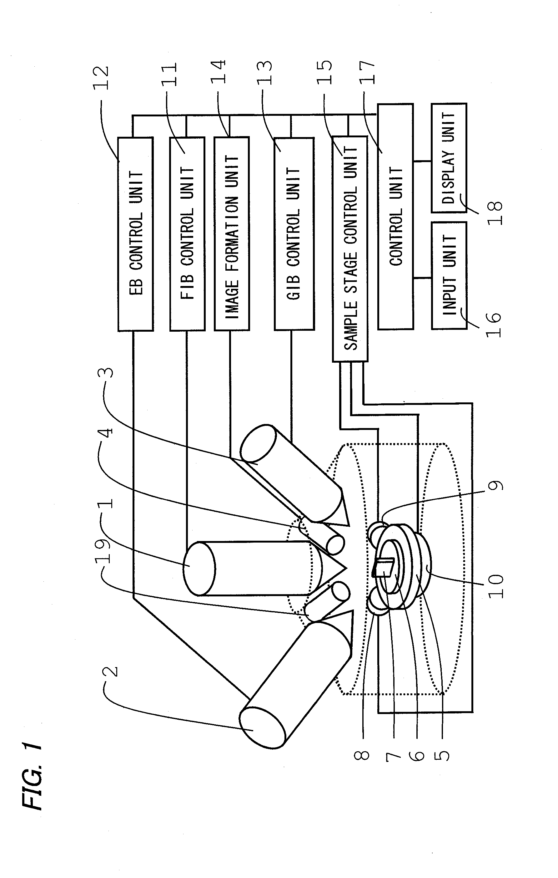
[0057]An exemplary embodiment will be described in which the thin sample 7 is processed by using the composite charged particle beam apparatus provided with the above-described second tilt mechanism.

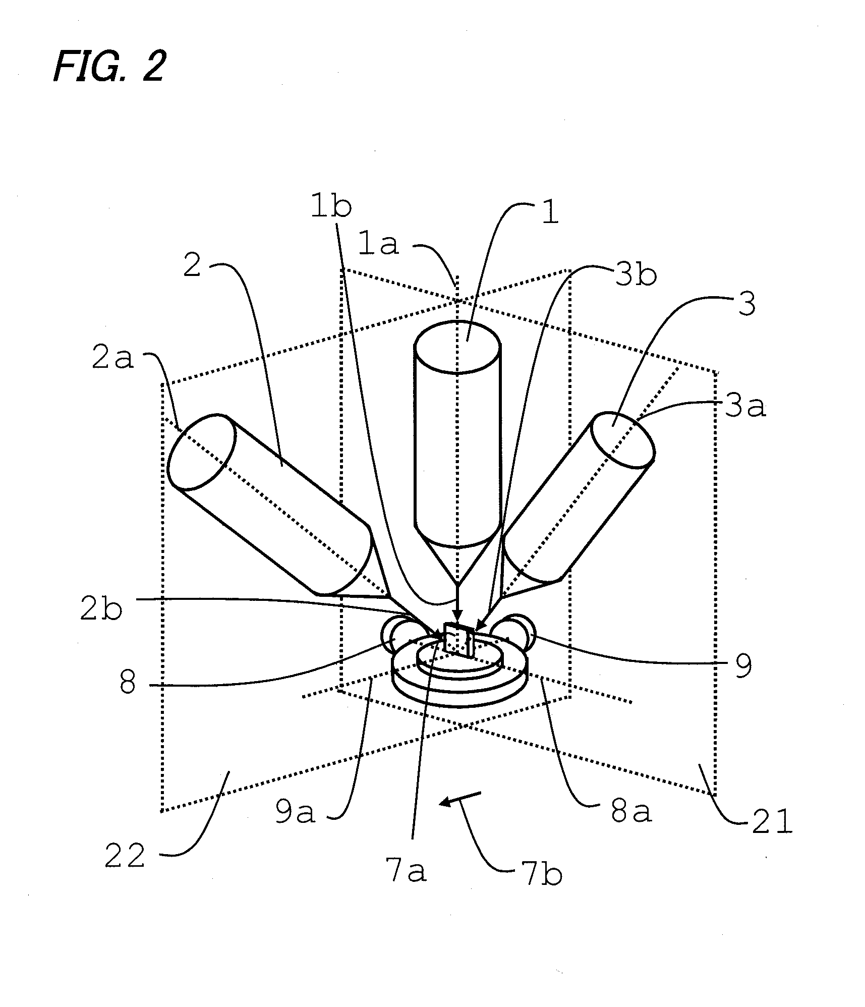
[0058]Referring to FIGS. 4A to 4D, a processing method will be described in which an azimuth angle of the GIB 3b is changed by tilting the sample stage 5 about the second tilt axis 9a. FIG. 4A illustrates arrangement of each column and the sample stage 5 on the second plane 22. FIG. 4B illustrates the arrangement of each column and the sample stage 5 on the first plane 21 at this time.

[0059]First, the cross-sectional surface 7a is formed on the thin sample 7 by using the FIB 1b. Then, the thin sample 7 is arranged so as to enable the cross-sectional surface 7a to be irradiated with the EB 2b. Then, the cross-sectional surface 7a is irradiated with the GIB 3b, and is subjected to the etching processing (first finishing processing). The cross-sectional surface 7a is irradiated with the EB ...

second exemplary embodiment

[0067]An exemplary embodiment will be described in which the thin sample 7 is processed by using the composite charged particle beam apparatus provided with a tilt sample holder 61 instead of the above-described second tilt mechanism

[0068]In the composite charged particle beam apparatus without the second tilt mechanism, it is not possible to change the azimuth angle of the GIB 3b which is incident on the upper surface 7c of the thin sample 7, only by tilting the thin sample 7 about the first tilt axis 8a. Therefore, it is adopted a configuration where a sample fixing surface 61a is provided which is tilted at a constant angle with respect to a sample installation surface 5a of the sample stage 5, the attachable and detachable tilt sample holder 61 is installed, and the sample stage 5 is tilted about the first tilt axis 8a in a state where the thin sample 7 is fixed to the tilt sample holder 61. In this manner, it is possible to perform the finishing processing by irradiating the cr...

third exemplary embodiment

[0075]Additional exemplary embodiment in which the thin sample 7 is processed by using the composite charged particle beam apparatus provided with the tilt sample holder 61 like the second exemplary embodiment will be described. In the present exemplary embodiment, the tilt sample holder 61 is used similarly to the second exemplary embodiment, but a rotary operation (rotation operation) is added in which the sample stage drive unit 10 (refer to FIG. 1) rotates the thin sample 7 in a plane during the processing.

[0076]FIGS. 10A and 10B are explanatory views for defining an “incidence angle” and an “azimuth angle” which are applied to the present exemplary embodiment. FIG. 10A illustrates the incidence angle, which is an angle in which the GIB 3b is incident on the thin sample 7. Specifically, the incidence angle herein is an angle in a direction perpendicular to the exposed cross-sectional surface 7a of the thin sample 7.

[0077]On the other hand, FIG. 10B illustrates the “azimuth angel...


PUM

PropertyMeasurementUnit
Angleaaaaaaaaaa

Abstract

A composite charged particle beam apparatus includes: a FIB column irradiating a thin sample with FIB; a GIB column irradiating the thin sample with GIB; a sample stage on which the thin sample is placed; a first tilt unit for tilting the thin sample about a first tilt axis of the sample stage, the first tilt axis being orthogonal to an FIB irradiation axis and being located inside a first plane formed by the FIB irradiation axis and a GIB irradiation axis; and a second tilt unit for tilting the thin sample about an axis which is orthogonal to the FIB irradiation axis and the first tilt axis.

Description

CROSS-REFERENCE TO RELATED APPLICATIONS[0001]The present application claims priority from Japanese Patent Application No. 2012-190490 filed on Aug. 30, 2012 and Japanese Patent Application No. 2013-174802 filed on Aug. 26, 2013, the contents of which are incorporated herein by reference.BACKGROUND[0002]1. Technical Field[0003]The present invention relates to a composite charged particle beam apparatus for preparing a thin sample by using an ion beam.[0004]2. Related Art[0005]There has been proposed a technology of preparing a thin sample used for transmission electron microscope (TEM) observation by using a focused ion beam (FIB) apparatus. Further, it has been known that gallium, which is an ion species, is injected to the thin sample by irradiation of the Focused Ion Beam so that a damage layer is formed.[0006]In recent years, as means for removing the damaged layer, finishing processing has been proposed in which the thin sample is irradiated with a gas ion beam (GIB) and the dam...

Claims


Application Information

Patent Timeline
IPC IPC(8): H01J37/30H01J37/02
CPCH01J37/02H01J37/3005H01J37/20H01J37/28H01J2237/20207H01J2237/28H01J2237/3174H01J2237/31749H01J2237/31745H01J37/26
Inventor ASAHATA, TATSUYASUZUKI, HIDEKAZUTORIKAWA, SHOTA
Owner HITACHI HIGH TECH SCI CORP
Why Eureka
Try Eureka