Ion-conducting composite electrolyte comprising path-engineered particles

a technology of composite electrolytes and path-engineered particles, which is applied in the direction of diaphragms, primary cells, fuel cells, etc., can solve the problems of limiting difficult manufacturing and incorporation into electrochemical devices, and polycrystalline ceramic electrolytes often exhibit poor mechanical properties, etc., to achieve the limit the ionic conductivity of the electrolyte, poor mechanical properties, and practical manufacturing

Active Publication Date: 2014-03-06
CORNING INC
View PDF5 Cites 43 Cited by
  • Summary
  • Abstract
  • Description
  • Claims
  • Application Information

AI Technical Summary

Benefits of technology

[0005]The present inventors have recognized significant unrealized potential in ion-conducting ceramic electrolytes and attribute this unrealized potential to a general tendency to turn to polycrystalline ceramic electrolytes, which are often more practical to manufacture than single crystal ceramic electrolytes. However, grain boundaries in polycrystalline ceramic electrolytes limit the ionic conductivity of the electrolyte. Additionally, polycrystalline ceramic electrolytes often exhibit poor mechanical properties and are often difficult to manufacture and incorporate into electrochemical devices. Ion-conducting composite electrolytes according to the subject matter of the present disclosure comprise path-engineered ion-conducting ceramic electrolyte particles positioned in a solid polymeric matrix and can be configured to confer flexibility and strain tolerance that exceeds that which is possible with a conventional ceramic electrolytes.

Problems solved by technology

However, grain boundaries in polycrystalline ceramic electrolytes limit the ionic conductivity of the electrolyte.
Additionally, polycrystalline ceramic electrolytes often exhibit poor mechanical properties and are often difficult to manufacture and incorporate into electrochemical devices.

Method used


Image

  • Ion-conducting composite electrolyte comprising path-engineered particles
  • Ion-conducting composite electrolyte comprising path-engineered particles
  • Ion-conducting composite electrolyte comprising path-engineered particles

Examples


Embodiment Construction

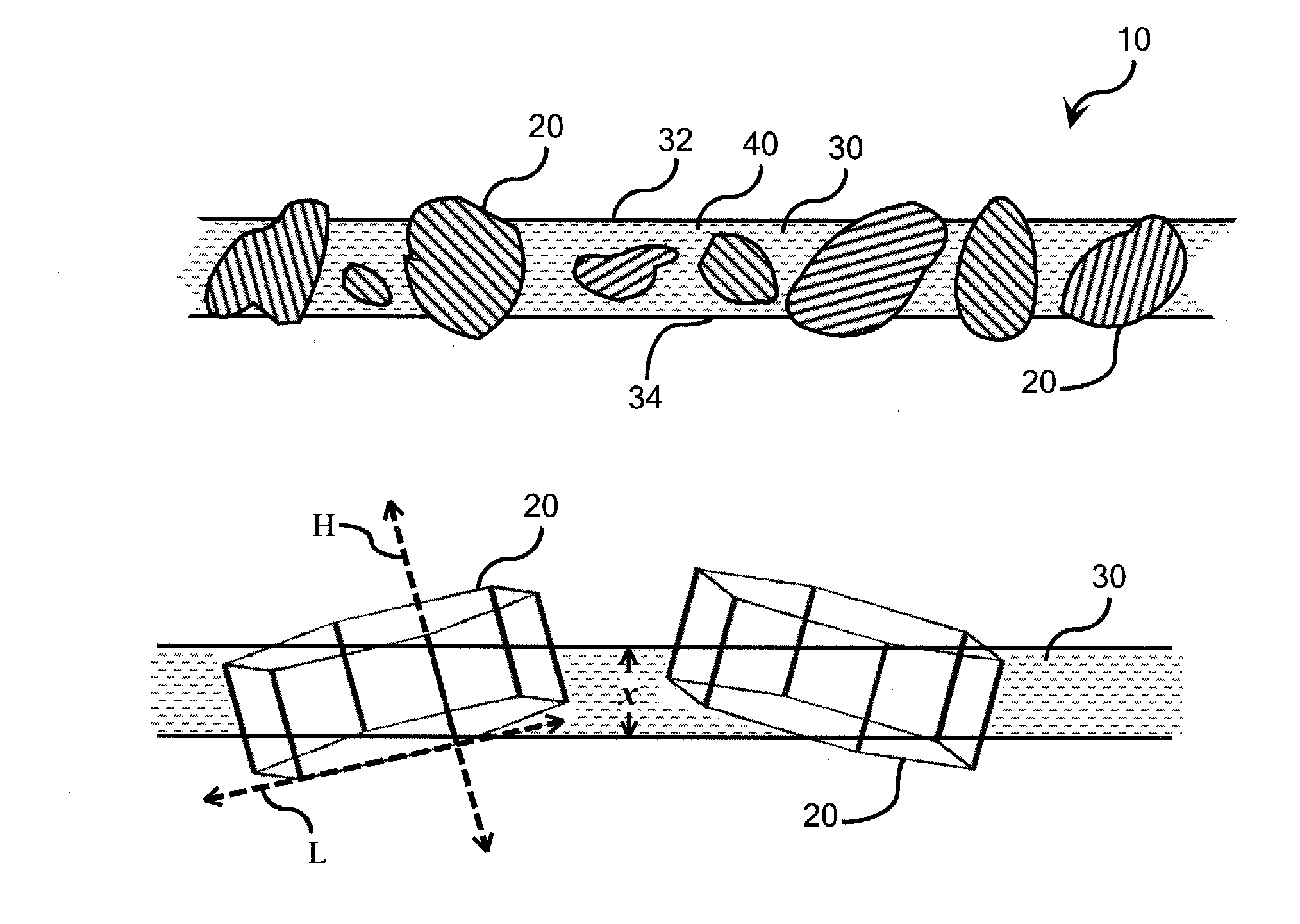
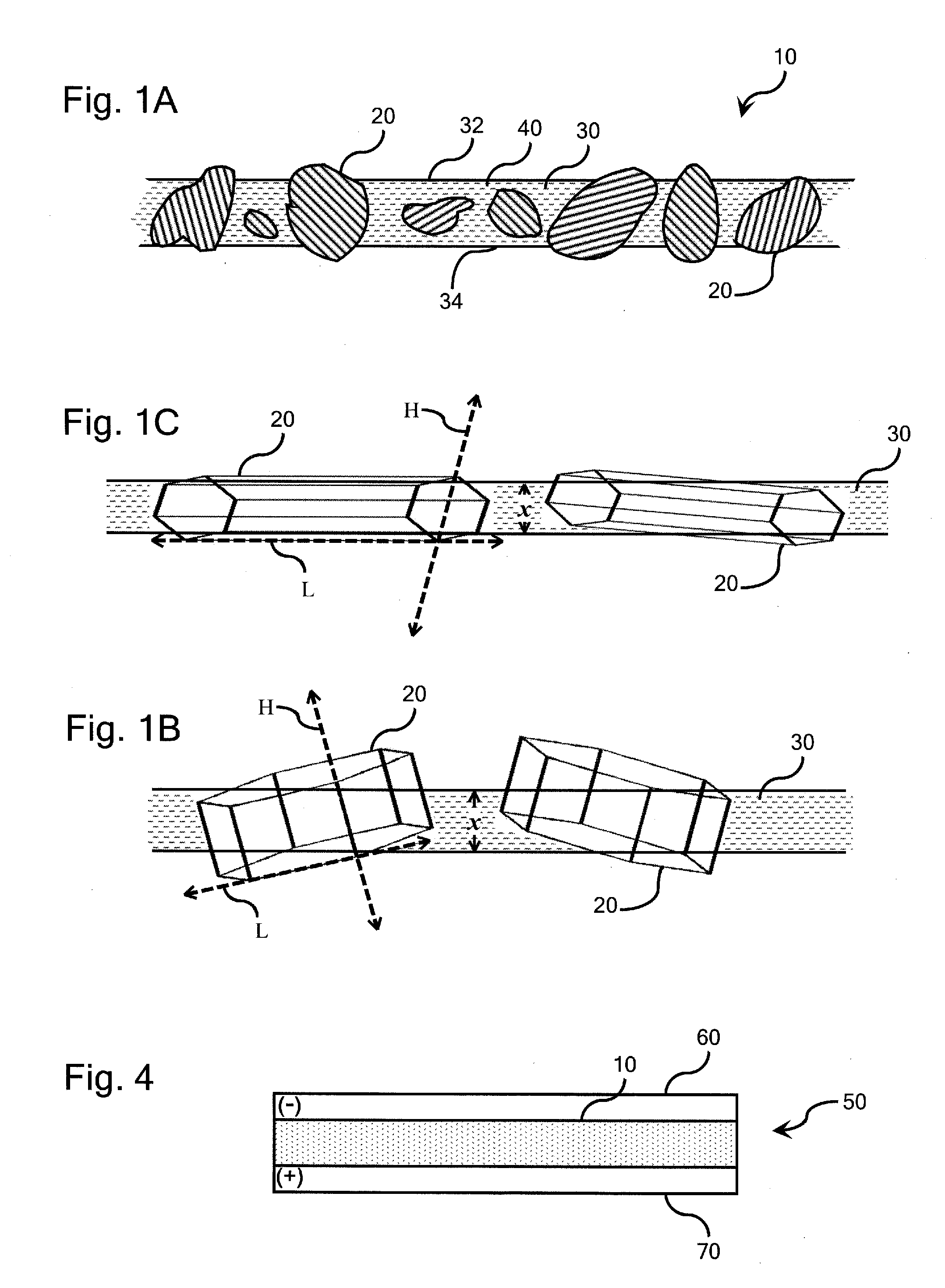
[0016]Referring initially to FIG. 1A, a portion of an ion-conducting composite electrolyte 10 is illustrated schematically and comprises path-engineered ion-conducting ceramic electrolyte particles 20, a solid polymeric matrix 30, and, optionally, a fiber stiffener component 40 distributed throughout the polymeric matrix 30. The respective shapes of the path-engineered particles 20 may vary significantly from particle to particle and is not illustrated with particular precision in FIG. 1A. Rather, the path-engineered particles 20 of FIG. 1A are merely presented to show their presence in the polymeric matrix 30 and to show that their size and shape will typically vary across the composite electrolyte 30. Similarly, the size and shape of the path-engineered particles illustrated in FIGS. 1B and 1C, described in further detail below, have been intentionally simplified for illustrative purposes.

[0017]As is illustrated in FIG. 1A, the polymeric matrix defines a pair of opposite major fac...


PUM

PropertyMeasurementUnit
sizeaaaaaaaaaa
sizeaaaaaaaaaa
ionic conductivityaaaaaaaaaa

Abstract

An ion-conducting composite electrolyte is provided comprising path-engineered ion-conducting ceramic electrolyte particles and a solid polymeric matrix. The path-engineered particles are characterized by an anisotropic crystalline structure and the ionic conductivity of the crystalline structure in a preferred conductivity direction H associated with one of the crystal planes of the path-engineered particle is larger than the ionic conductivity of the crystalline structure in a reduced conductivity direction L associated with another of the crystal planes of the path-engineered particle. The path-engineered particles are sized and positioned in the polymeric matrix such that a majority of the path-engineered particles breach both of the opposite major faces of the matrix body and are oriented in the polymeric matrix such that the preferred conductivity direction H is more closely aligned with a minimum path length spanning a thickness of the matrix body than is the reduced conductivity direction L.

Description

BACKGROUND[0001]1. Field[0002]The present disclosure relates to ion-conducting electrolytes and assemblies incorporating ion-conducting electrolytes.[0003]2. Technical Background[0004]Ion-conducting electrolytes have been proposed for use in a wide variety of technological applications including lithium ion batteries, sodium sulfur batteries, solid oxide fuel cells, oxygen separators, electrolyzers, sensors, chemical reactors, etc.BRIEF SUMMARY[0005]The present inventors have recognized significant unrealized potential in ion-conducting ceramic electrolytes and attribute this unrealized potential to a general tendency to turn to polycrystalline ceramic electrolytes, which are often more practical to manufacture than single crystal ceramic electrolytes. However, grain boundaries in polycrystalline ceramic electrolytes limit the ionic conductivity of the electrolyte. Additionally, polycrystalline ceramic electrolytes often exhibit poor mechanical properties and are often difficult to ...

Claims


Application Information

Patent Timeline
Patent Type & Authority Applications(United States)
IPC IPC(8): H01M8/10G01N27/40C25B13/08H01M10/0562H01M6/36H01M50/434H01M50/497
CPCH01M8/1058H01M10/0562G01N27/40C25B13/08H01M6/36C08J5/22H01M8/1048H01M10/0525H01M10/056H01M6/18H01M2300/0091C25B13/04H01G11/56Y02E60/50Y02E60/10B29C64/153B29C64/165H01M50/446H01M50/434H01M50/497Y02E60/13
Inventor BADDING, MICHAEL EDWARDBROWN, JACQUELINE LESLIEFINK, KATHERINE A.GAGOV, ATANAS VALENTINOVTANNER, CAMERON WAYNE
Owner CORNING INC
Why Eureka
Try Eureka