METHOD OF CONTROLLING THE AMOUNT OF Cu DOPING WHEN FORMING A BACK CONTACT OF A PHOTOVOLTAIC CELL

a photovoltaic cell and back contact technology, applied in the field of controlling the amount of cu doping when forming a back contact of a photovoltaic device, can solve the problems of deterioration of solar cell efficiency, graphite-paste back contacts are not generally viewed as suitable, and the back contacts of conventional metals are not generally suitabl

Active Publication Date: 2014-03-06
FIRST SOLAR INC (US)
View PDF2 Cites 6 Cited by
  • Summary
  • Abstract
  • Description
  • Claims
  • Application Information

AI Technical Summary

Problems solved by technology

Due to the high work function of CdTe, conventional metal back contacts are not generally viewed as being suitable.
However, these graphite-paste back contacts tend to degrade significantly over time, as can be shown via accelerated lifetime testing.
The degradation of the back contact electrodes undesirably leads to degradation of the solar cell efficiency, on a long-term basis.
While the introduction of copper into the back contact has been known, it is also known that the presence of copper in the final device may lead to the degradation of the device efficiency over time.

Method used


Image

  • METHOD OF CONTROLLING THE AMOUNT OF Cu DOPING WHEN FORMING A BACK CONTACT OF A PHOTOVOLTAIC CELL
  • METHOD OF CONTROLLING THE AMOUNT OF Cu DOPING WHEN FORMING A BACK CONTACT OF A PHOTOVOLTAIC CELL
  • METHOD OF CONTROLLING THE AMOUNT OF Cu DOPING WHEN FORMING A BACK CONTACT OF A PHOTOVOLTAIC CELL

Examples


example 1

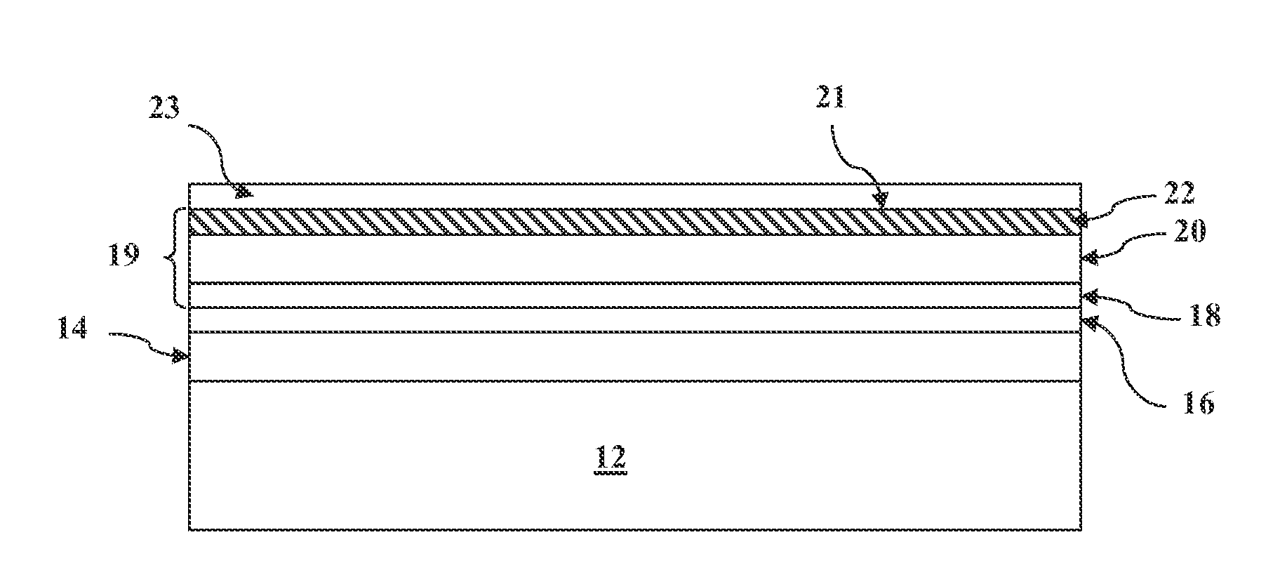
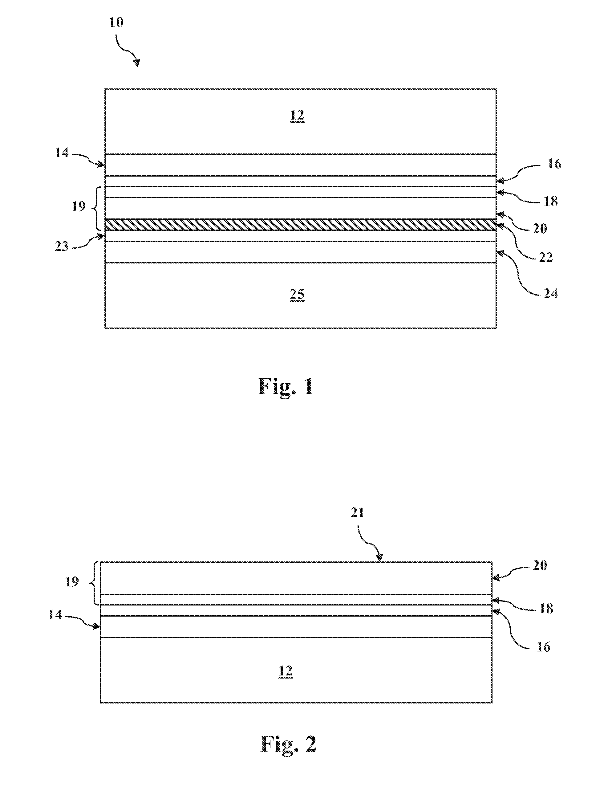
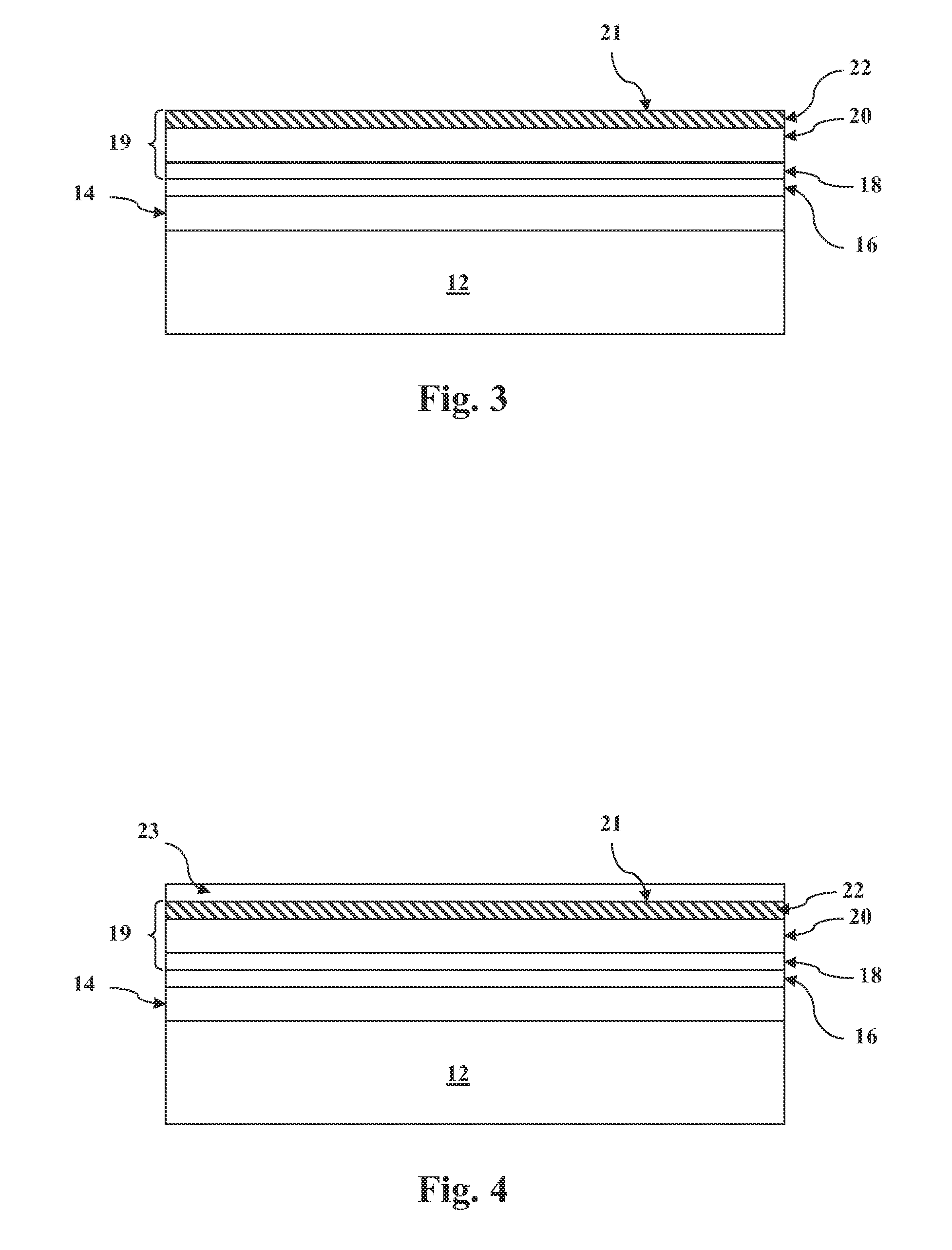
[0066]Mixtures of CuCl2 and CdCl2 were sprayed (20 sec) onto the exposed surface of the p-type absorber layer according to the following concentrations: (1a) 37.5 g / L CdCl2 and 0.1 g / L CuCl2; (1b) 75 g / L CdCl2 and 0.1 g / L CuCl2; (1c) 150 g / L CdCl2 and 0.1 g / L CuCl2; and (1d) 150 g / L CdCl2 and 0.05 g / L CuCl2.

[0067]Samples were annealed at either 175° C. or 185° C. for 20 minutes, first condition was also annealed at 200° C. for 10 minutes. The samples were then rinsed and an inert graphite layer and metal layer were applied. As a control, a sample was annealed with CuCl2 (1.8 g / L at 175° C. for 20 minutes) and an inert graphite and metal layer were applied.

[0068]The highest efficiency (about 13.7%) and fill factor (about 72-73) was obtained with sample 1c (150 g / L CdCl2 and 0.1 g / L CuCl2 annealed at 185° C.). Fill factor appeared to increase with increase in CdCl2 concentration and higher Cu concentration. Voc appeared to increase with higher temperature and lower Cu concentration.

example 2

[0069]Mixtures of CuCl2 and MnCl2 were sprayed (20 sec) onto the exposed surface of the p-type absorber layer according to the following concentrations: (2a) 26 g / L MnCl2 and 0.1 g / L CuCl2; (2b) 26 g / L MnCl2 and 0.45 g / L CuCl2; (2c) 105 g / L MnCl2 and 0.1 g / L CuCl2; and (2d) 150 g / L MnCl2 and 0.1 g / L CuCl2.

[0070]Samples were annealed at either 175° C. or 185° C. for 20 minutes. The samples were then rinsed and an inert graphite layer and metal layer were applied. As a control, a sample was annealed with CuCl2 (1.8 g / L at 175° C. for 20 minutes) and an inert graphite and metal layer were applied.

[0071]The highest efficiency was obtained with samples 2c and 2d annealed at 185° C. At 175° C., the highest performing condition was 2b.

example 3

[0072]Mixtures of CuCl2 and ZnCl2 were sprayed (20 sec) onto the exposed surface of the p-type absorber layer according to the following concentrations: (3a) 30.5 g / L ZnCl2 and 0.45 g / L CuCl2; (3b) 30.5 g / L ZnCl2 and 0.1 g / L CuCl2; (3c) 121 g / L ZnCl2 and 0.1 g / L CuCl2; and (3d) 150 g / L ZnCl2 and 0.1 g / L CuCl2.

[0073]Samples were annealed at either 175° C. or 185° C. for 20 minutes. The samples were then rinsed and an inert graphite layer and metal layer were applied. As a control, a sample was annealed with CuCl2 (1.8 g / L at 175° C. for 20 minutes) and an inert graphite and metal layer were applied.

[0074]The highest efficiency was obtained with samples 3a, for both annealing temperatures. Fill factor increased with increase in CuCl2 concentration and temperature, decrease in ZnCl2 concentration. Voc increased with decrease in CuCl2 concentration and increase in ZnCl2 concentration. Voc's higher for lower ZnCl2 concentrations and 0.45 g / L CuCl2 were almost equivalent to higher ZnCl2 c...


PUM

PropertyMeasurementUnit
concentrationaaaaaaaaaa

Abstract

Methods for preparing an exposed surface of a p-type absorber layer of a p-n junction for coupling to a back contact in the manufacture of a thin film photovoltaic device are provided. The method can include: applying a treatment solution onto the exposed surface defined by the p-type absorber layer of cadmium telluride; and annealing the device with the p-type absorber layer in contact with the treatment solution to form a tellurium-enriched region in the p-type absorber layer at the exposed surface. The treatment solution comprises a chlorinated compound component that is substantially free from copper, a copper-containing metal salt, and a solvent.

Description

FIELD OF THE INVENTION[0001]The subject matter disclosed herein relates generally to methods of controlling the amount of copper (Cu) when forming a back contact of a photovoltaic device.BACKGROUND OF THE INVENTION[0002]Thin film photovoltaic (PV) modules (also referred to as “solar panels”) based on cadmium telluride (CdTe) paired with cadmium sulfide (CdS) as the photo-reactive components are gaining wide acceptance and interest in the industry. CdTe is a semiconductor material having characteristics particularly suited for conversion of solar energy to electricity. For example, CdTe has an energy bandgap of about 1.45 eV, which enables it to convert more energy from the solar spectrum as compared to lower bandgap semiconductor materials historically used in solar cell applications (e.g., about 1.1 eV for silicon). Also, CdTe converts radiation energy in lower or diffuse light conditions as compared to the lower bandgap materials and, thus, has a longer effective conversion time o...

Claims


Application Information

Patent Timeline
Patent Type & Authority Applications(United States)
IPC IPC(8): H01L31/18
CPCH01L31/073H01L31/1864Y02E10/543Y02P70/50
Inventor CLARK, LAURA ANNELUCAS, TAMMY JANEMETZGER, WYATT KEITHDEMTSU, SAMUEL H.DICKERSON, DAVID JOSEPHWILSON, LAURA JEANSADEGHI, MEHRAN
Owner FIRST SOLAR INC (US)
Why Eureka
Try Eureka