Magnesium barium thioaluminate and related phosphor materials

a phosphor material and magnesium barium thioaluminate technology, applied in the field of magnesium barium thioaluminate and related phosphor materials, can solve the problems of increased performance, degrade the properties of phosphor materials, and insufficient accuracy of shadow mask techniques

Inactive Publication Date: 2002-09-05
IFIRE TECH INC
View PDF0 Cites 40 Cited by
  • Summary
  • Abstract
  • Description
  • Claims
  • Application Information

AI Technical Summary

Problems solved by technology

For displays with high resolution, however, the shadow mask technique does not provide adequate accuracy, and photolithographic methods must be employed.
Some phosphor materials, for example strontium sulphide are susceptible to hydrolysis, and water and aprotic solvents may degrade the properties of the phosphor materials.
However, such a design modification demands increased performance from the phosphor materials used for the red and green phosphor materials, and requires the use of higher display operating voltages.
The higher operating voltages increase the power consumption of the display, decrease the reliability and increase the cost of operating the electronics of the display.
However, even with the enhanced luminosity that is obtained, thick film electroluminescent displays have not achieved the phosphor luminance and colour coordinates needed to be fully competitive with cathode ray tube (CRT) displays.
The filter substantially attenuates the luminosity of the phosphor, and it is therefore difficult to achieve adequate display luminosity.
These include cerium-activated alkaline earth thiogallate compounds, which give good blue colour coordinates, but have relatively poor luminosity and stability.

Method used


Image

  • Magnesium barium thioaluminate and related phosphor materials
  • Magnesium barium thioaluminate and related phosphor materials
  • Magnesium barium thioaluminate and related phosphor materials

Examples


example ii

[0067] A series of magnesium barium thioaluminate thin film phosphors materials were prepared by blending powders of aluminum sulphide, barium sulphide, magnesium sulphide and europium sulphide in the desired ratios and making pressed pellets of the blended powders. In the series of phosphor materials, the fraction "a" of barium replaced by magnesium in the formula Mg.sub.aBa.sub.1-aAL.sub.2 S.sub.4:Eu was varied in increments of 0.1 over the range of a=0 to a=0.5. All of the phosphor materials had a nominal concentration of europium corresponding to 3 atomic percent of the sum of the magnesium and barium concentrations.

[0068] The pellets were placed in an alumina boat and fired in a nitrogen atmosphere using a belt furnace, using a temperature profile such that the films were subject to a nominal peak temperature of 900.degree. C. for about 7 minutes. The actual sample temperature may have been lower than 900.degree. C. because of the thermal capacity of the alumina boat.

[0069] The...

example iii

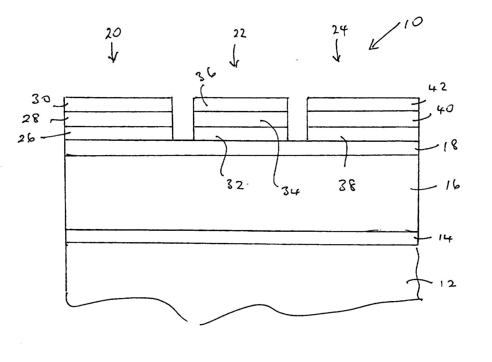
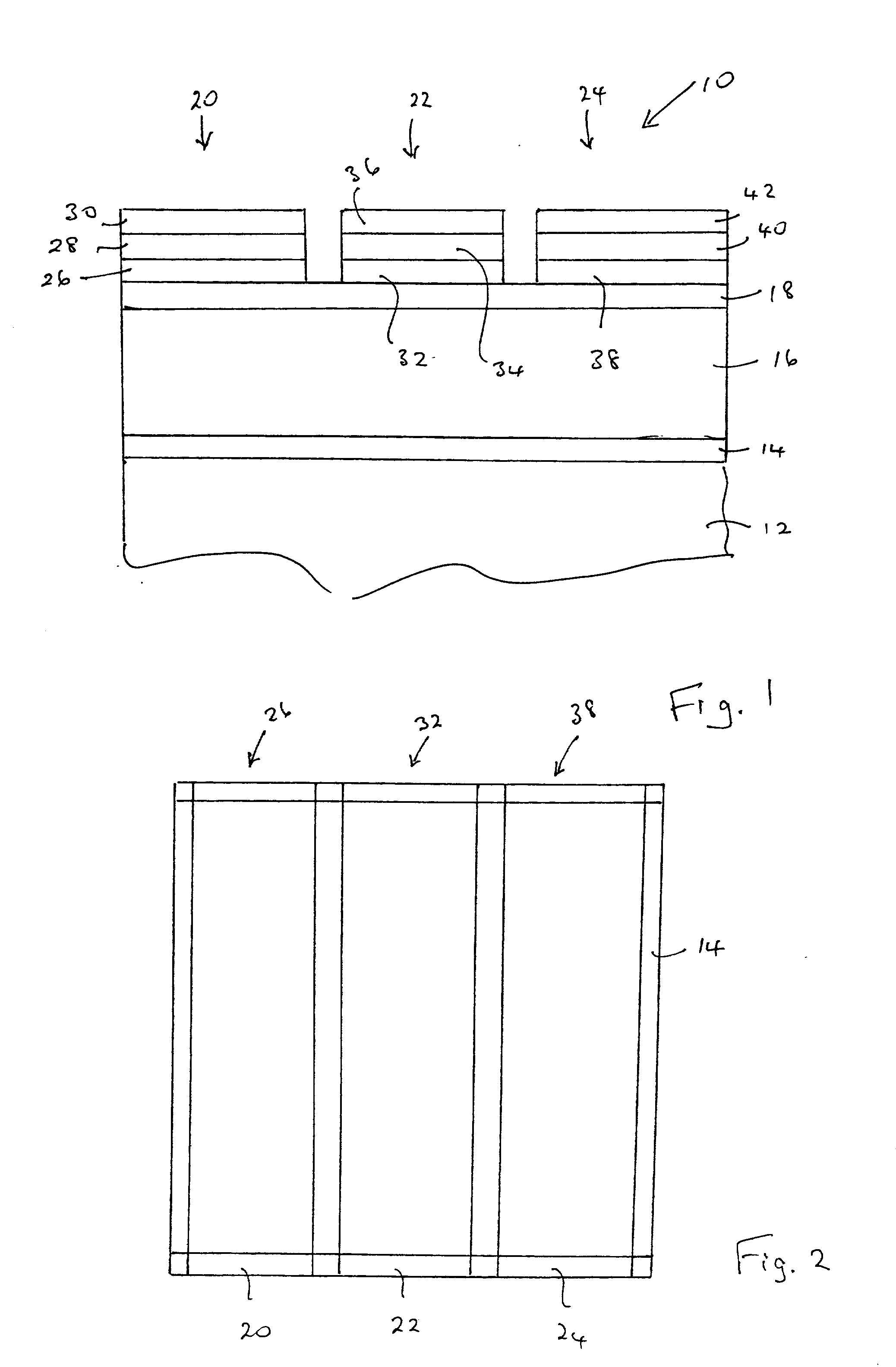
[0076] Magnesium barium thioaluminate materials of the formula Mg.sub.aBa.sub.1-aAl.sub.2S.sub.4:Eu, with a nominal value of a=0.5 and a europium concentration equal to 3 atomic percent of the sum of the magnesium and barium concentrations, were deposited as thin films on thick film dielectric structures. The deposition method used was dual source electron beam evaporation, in which one source was a pressed pellet of aluminum sulphide (Al.sub.2S.sub.3) and the other source was a pressed pellet consisting of a mixture of barium sulphide, magnesium sulphide and europium sulphide. The phosphor films were annealed at a nominal temperature of 850.degree. C. under nitrogen.

[0077] It should be noted that the stated composition for the materials in this example is for the source materials, and the composition of the deposited films may vary from these compositions.

[0078] The electroluminescent emission of the resultant phosphor showed the same blue shift with respect to material not contain...

example iv

[0080] The procedure of Example III was repeated, except that europium oxide (Eu.sub.2O.sub.3) was used instead of europium sulphide. The remaining compounds were aluminum sulphide, barium sulphide and magnesium sulphide, as in Example III. The nominal value of a in the formula of Example III was 0.5. The europium concentration was 3 atomic percent of the sum of the magnesium and barium concentrations.

[0081] It was found that the resultant phosphor had the same characteristics as the phosphor of Example III that had been formed using europium sulphide. It is therefore believed that europium sulphide may be replaced in whole or in part with europium oxide for europium concentrations of up to 3 atomic percent.


PUM

PropertyMeasurementUnit
temperatureaaaaaaaaaa
temperaturesaaaaaaaaaa

Abstract

A phosphor and a method of deposition. The phosphor comprises a composition of the formula M'aBa1-aM''2M'''4':RE, where M' is at least one element selected from magnesium and calcium, M'' is at least one element selected from aluminum, gallium and indium, M''' is at least one element selected from sulphur, selenium and tellurium, RE is at least one rare earth element, especially europium or cerium, and 0<a<1. Deposition is preferably by dual source electron beam deposition. The phosphor may be annealed. The phosphor provides a high luminosity blue emission that does not require an optical filter to achieve acceptable colour coordinates for the blue sub-pixel element for a full colour thin film or thick film electroluminescent display. The blue sub-pixel pixel performance meets the luminosity and colour temperature specifications for current generation cathode ray tube displays.

Description

[0001] The present invention relates to a high luminosity blue phosphor. In particular, the present invention relates to a blue phosphor that may be used without an optical filter to provide acceptable colour coordinates for the blue sub-pixel element of a full-colour electroluminescent display. In preferred embodiments, the electroluminescent displays employ thick film dielectric layers with a high dielectric constant. In embodiments, the phosphor is M'.sub.aBa.sub.1-aM".sub.2M'".sub.4.RE, where M' is selected from magnesium and calcium, M" is selected from aluminum, gallium and indium, M'" is selected from sulphur, selenium and tellurium, and RE is a rare earth element, especially europium and cerium.BACKGROUND TO THE INVENTION[0002] Thin film electroluminescent (TFEL) displays are known and are typically fabricated on glass substrates. Electroluminescent displays with thin film phosphors employing thick film dielectric layers fabricated on ceramic substrates, as exemplified by U....

Claims


Application Information

Patent Timeline
Patent Type & Authority Applications(United States)
IPC IPC(8): C01F7/70C09K11/00C09K11/08C09K11/62C09K11/64C09K11/77C09K11/88C23C14/06H05B33/14
CPCC09K11/7703C09K11/7731C09K11/886C23C14/0623H05B33/14
Inventor CHEONG, DAN DAEWEONWU, XINGWEI
Owner IFIRE TECH INC
Why Eureka
Try Eureka