Implant deployment apparatus

a technology for deploying equipment and implants, applied in the field of implants, can solve the problems of high incidence of repeat intervention, long recovery time after surgery, morbidity and mortality,

Inactive Publication Date: 2014-03-13
WL GORE & ASSOC INC
View PDF5 Cites 8 Cited by
  • Summary
  • Abstract
  • Description
  • Claims
  • Application Information

AI Technical Summary

Benefits of technology

[0016]The present invention generally involves a delivery system for an implant, such as a stent or stent-graft. The delivery system generally comprises a sheet of material adapted to extend around at least a portion of a collapsed implant, such as a collapsed stent or stent-graft. The sheet of material may form a tubular member when extending around at least a portion of a collapsed member. The system also may include a coupling member for coupling portions of the sheet together to maintain the implant in its collapsed state during delivery to a desired site in a mammalian body. With this construction a smooth interface between the collapsed stent and a vessel lumen, as compared to thread-like restraining members, may be achieved.
[0017]According to another aspect of the invention, the sheet may be constructed of a thin material which does not significantly contribute to the structural rigidity or cross-sectional profile to the delivery assembly. This construction may also eliminate the need for external sheathing or a guide catheter and is believed to advantageously increase the ability of the surgeon to deliver the device to relatively remote sites and through small tortuous vasculature. In addition, the sheet may comprise implantable material so that after release it may remain with the stent at the desired site.
[0018]According to another embodiment of the invention, an assembly comprising a stent and a restraining member coupled to the stent is provided. The stent has a collapsed and an expanded state and the restraining member comprises a sheet of material adapted to be wrapped around at least a portion of the stent when the stent is in the collapsed state. Portions of the sheet are adapted for coupling to one another to maintain the sheet wrapped around at least or portion of the stent in its collapsed state. Thus, in one configuration, portions of the sheet are releasably coupled to one another so that the sheet maintains the stent in its collapsed state.
[0019]According to another aspect of the invention, the portions of the sheet that may be coupled to one another may be coupled with a filament or thread-like member. The stent may be expanded (or allowed to expand when a self-expanding stent is used) after the thread-like coupling member is removed such as by being remotely pulled by a pull line, which may be an extension of the coupling member. Since the pull line may also have a thread-like low profile, friction between with the catheter, through which the pull line is pulled, and the pull line is minimized. It is believed that such construction may further facilitate deployment accuracy.
[0020]According to another aspect of the invention, multiple restraining members may be used. Alternatively, multiple coupling members may be used to couple multiple portions of one of more restraining members. These constructions can reduce deployment time and may reduce the time in which fluid flow may disturb the position of the implant as it is deployed.

Problems solved by technology

Shortcomings of this procedure include the morbidity and mortality associated with surgery, long recovery times after surgery, and the high incidence of repeat intervention needed due to limitations of the graft or of the procedure.
Generally, the mechanisms described above involve a number of components that may increase operational complexity.
In addition, the size and mechanical properties of these mechanisms may limit deliverability of implants in small vessels.
Delivery accuracy also may be a problem as discussed.
The diameter of conventional telescoping stent sheaths may contribute to undesirable friction with the delivery catheter as the sheath is pulled from the stent and over a push rod during deployment.
This may make deployment accuracy difficult to control.
Push rods, which are used to push the stent through the delivery catheter and which typically have a length of up to about 100 cm, also may contribute to undesirable friction with the catheter.
This problem may be exacerbated where the catheter bends along its path in the vasculature.

Method used


Image

  • Implant deployment apparatus
  • Implant deployment apparatus
  • Implant deployment apparatus

Examples


Embodiment Construction

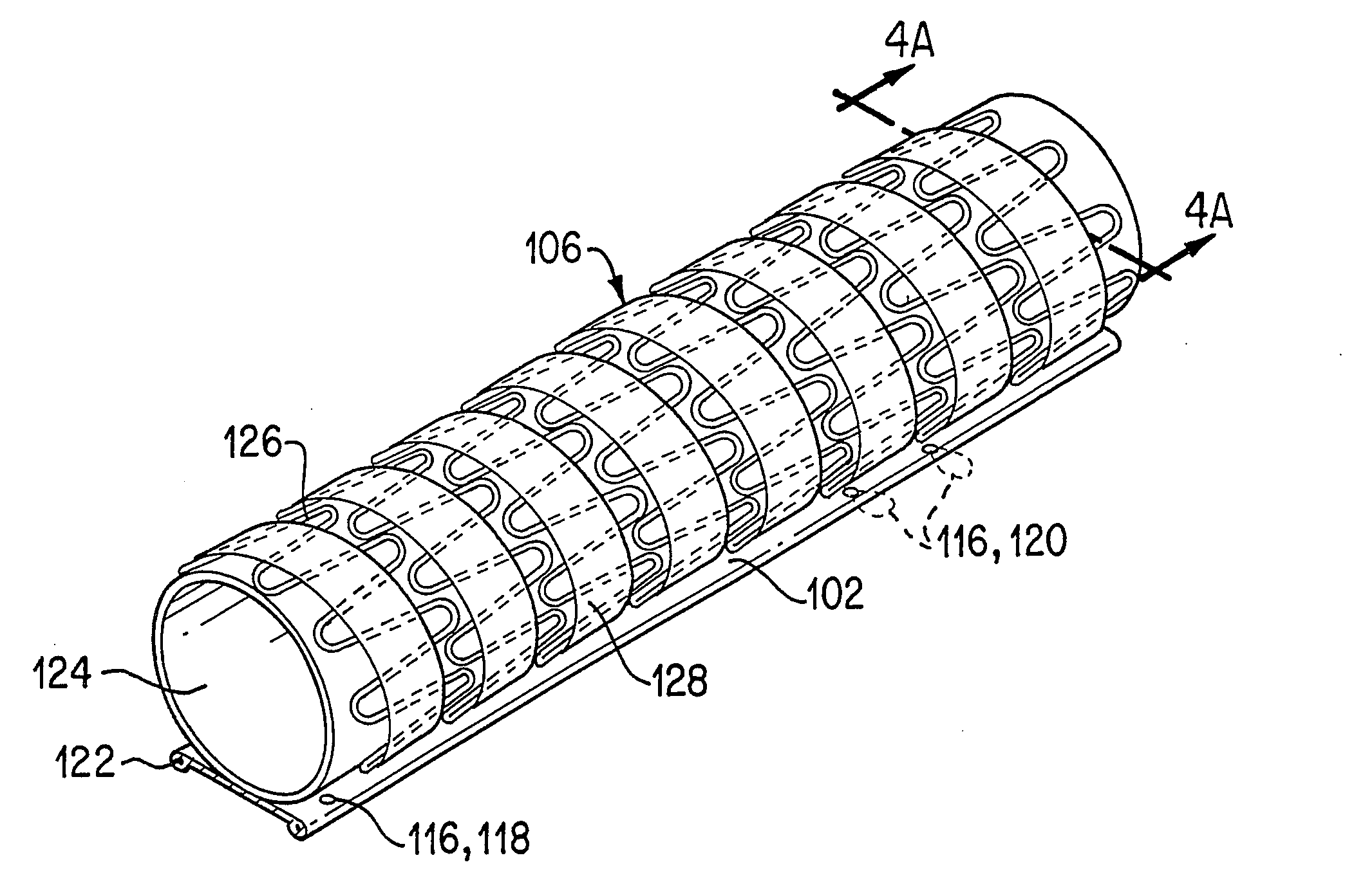
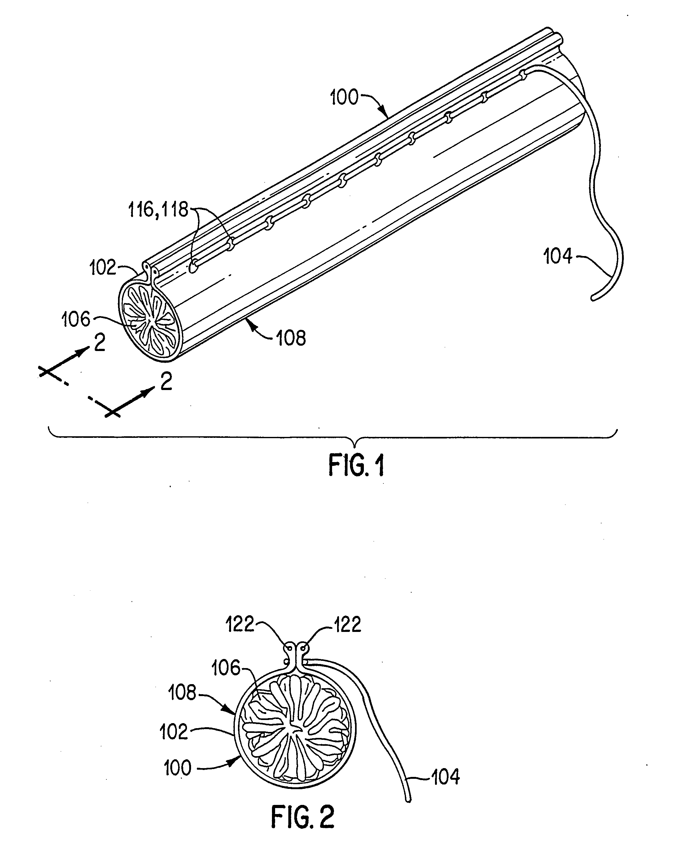
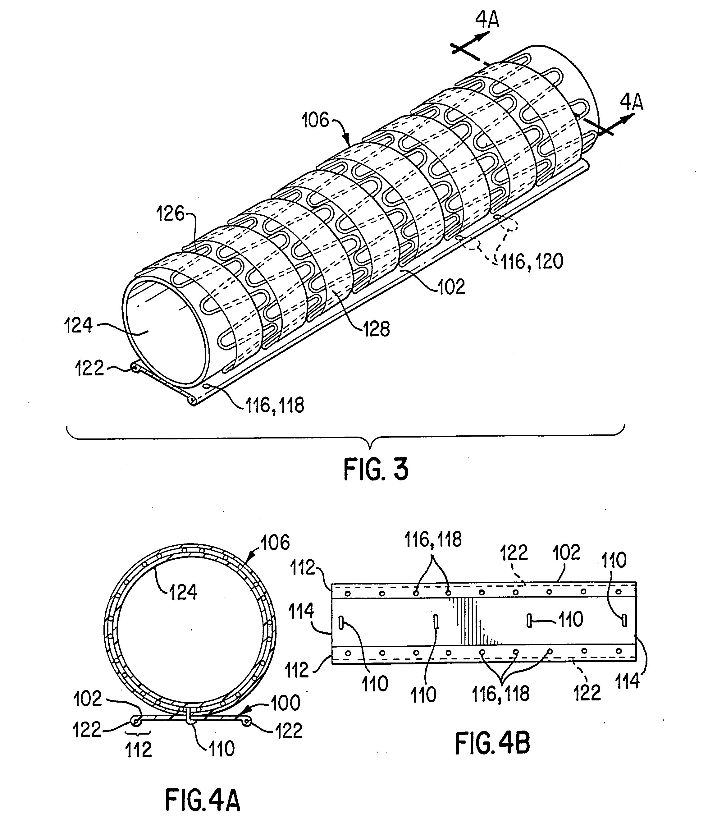
[0069]Referring to the drawings in detail wherein like numerals indicate like elements, delivery systems for delivering implants or devices, such as stents or stent-grafts, to a desired site in mammalian vasculature are shown in accordance with the principles of the present invention. The delivery systems of the present invention generally include a restraining member that is adapted and configured for surrounding at least a portion of a collapsed or compressed implant and a coupling member(s) for releasably coupling portions of the restraining member to one another to maintain the implant in its collapsed or compressed state.

[0070]Referring to FIGS. 1-4, an implant delivery system constructed in accordance with the present invention is shown. Delivery system (100), generally includes a restraining member (102), which as shown may be in the form of a sheet of material, and a coupling member (104) for releasably coupling portions of the restraining member to one another. The restrain...


PUM


Abstract

A delivery system including a restraining member maintains a collapsed implant in its collapsed state for delivery through a small passageway to a desired site in a mammalian body. Once the implant is positioned at the desired site, the restraining member is released so that the stent may expand or be expanded to its expanded state. In a preferred embodiment, the restraining member comprises a sheet of material that surrounds at least a portion of the collapsed stent. Portions of the restraining member are releasably coupled to one another with a low profile thread-like member or suture.

Description

BACKGROUND OF THE INVENTION[0001]1. Technical Field[0002]This invention relates generally to implants for repairing ducts and passageways in the body. More specifically, the invention relates to implant deployment apparatus.[0003]2. Background Art[0004]Treatment or isolation of vascular aneurysms or of vessel walls which have been thickened or thinned by disease has traditionally been performed via surgical bypassing with vascular grafts. Shortcomings of this procedure include the morbidity and mortality associated with surgery, long recovery times after surgery, and the high incidence of repeat intervention needed due to limitations of the graft or of the procedure.[0005]Vessels thickened by disease may be treated less invasively with stents which mechanically hold vessels open. In some instances, stents may be used subsequent to or as an adjunct to a balloon angioplasty procedure. Stents also have been described in conjunction with grafts where the graft is intended to provide a g...

Claims


Application Information

Patent Timeline
Patent Type & Authority Applications(United States)
IPC IPC(8): A61F2/07A61F2/00A61F2/06A61F2/88A61F2/90
CPCA61F2/07A61F2/848A61F2/88A61F2/90A61F2/954A61F2/97A61F2002/067A61F2002/075A61F2002/8486A61F2002/9511A61F2250/0059A61F2/89A61F2220/0016A61F2220/005A61F2220/0075A61F2230/001A61F2/9522A61F2/9525
Inventor LEOPOLD, ERIC W.TRAUTMAN, JOSEPHTHORNTON, TROYPAI, SURESH S.CHAN, RANDY S.BRETON, THOMAS G.
Owner WL GORE & ASSOC INC
Why Eureka
Try Eureka