
Ammunition feed system for firearm

Inactive Publication Date: 2014-03-20
MENINAS
View PDF0 Cites 21 Cited by
  • Summary
  • Abstract
  • Description
  • Claims
  • Application Information

AI Technical Summary

Benefits of technology

The present invention is a firearm cartridge feeding system that has advantages such as being able to be loaded with cartridges and stored for long periods of time without damaging the power spring. It can be easily wound to apply tension on the power spring only when necessary, extending the life of the power spring. The system is mainly constructed from composite materials which aid in contributing to its lightweight, weather-resistant, and natural lubricity. However, some components such as springs are made of metals that resist rust and corrosion. The technical effects of the invention are improved durability and reliability of the firearm cartridge feeding system.

Problems solved by technology

Single shot, single barreled, muzzle loading flintlock musket firearms of the late 1700's and early 1800's were a great advancement in the history of firearms, but they did not offer the marksman with a quick subsequent shot(s).
If the target was missed and the marksman wanted to reload, a time consuming process of reloading involved pouring gunpowder down the barrel, and ramming a projectile on top of the powder, followed by priming the breach before being able to fire once again.
In a life or death situation, the time to reload was unacceptable.
However, the capacity of box type magazines are limited because they have the physical characteristic of extending significantly below the firearm.
Also many drum type magazines become jammed and fail to feed, and it is difficult to correct the jammed drum type cartridges.
As with a conventional box magazines or drum magazines, when a magazine is stored with cartridges loaded into the magazine, the spring becomes weakened because of the constant tension being placed on the follower spring for long periods of time.

Method used


Image

  • Ammunition feed system for firearm
  • Ammunition feed system for firearm
  • Ammunition feed system for firearm

Examples


Embodiment Construction

[0090]The following description of the preferred embodiment(s) is merely exemplary in nature and is in no way intended to limit the invention, its application, or uses.

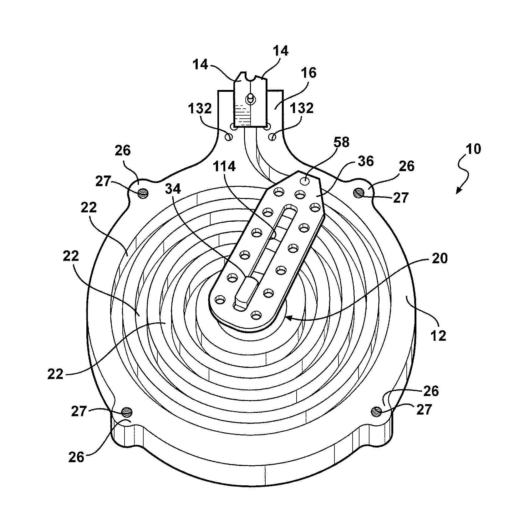
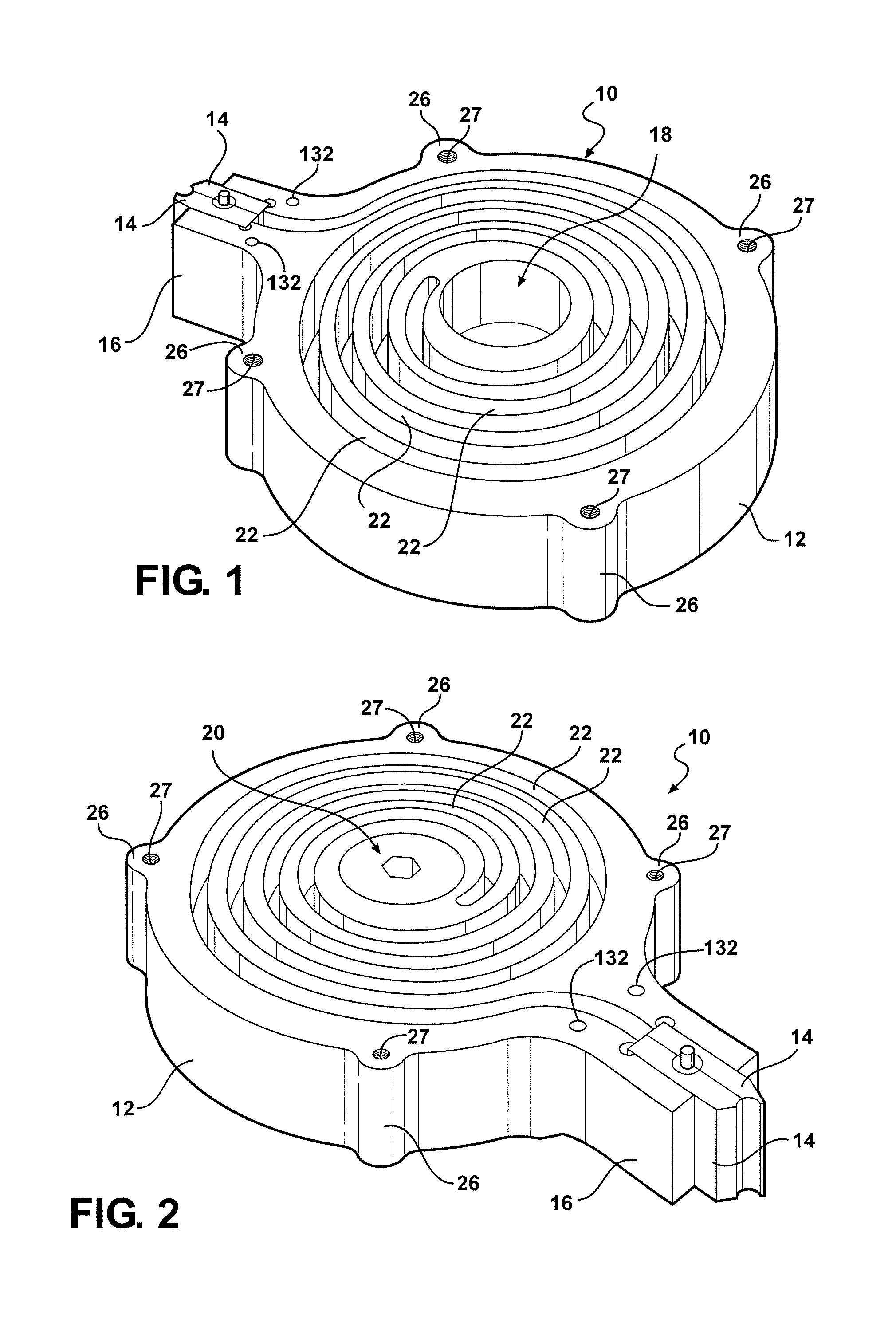
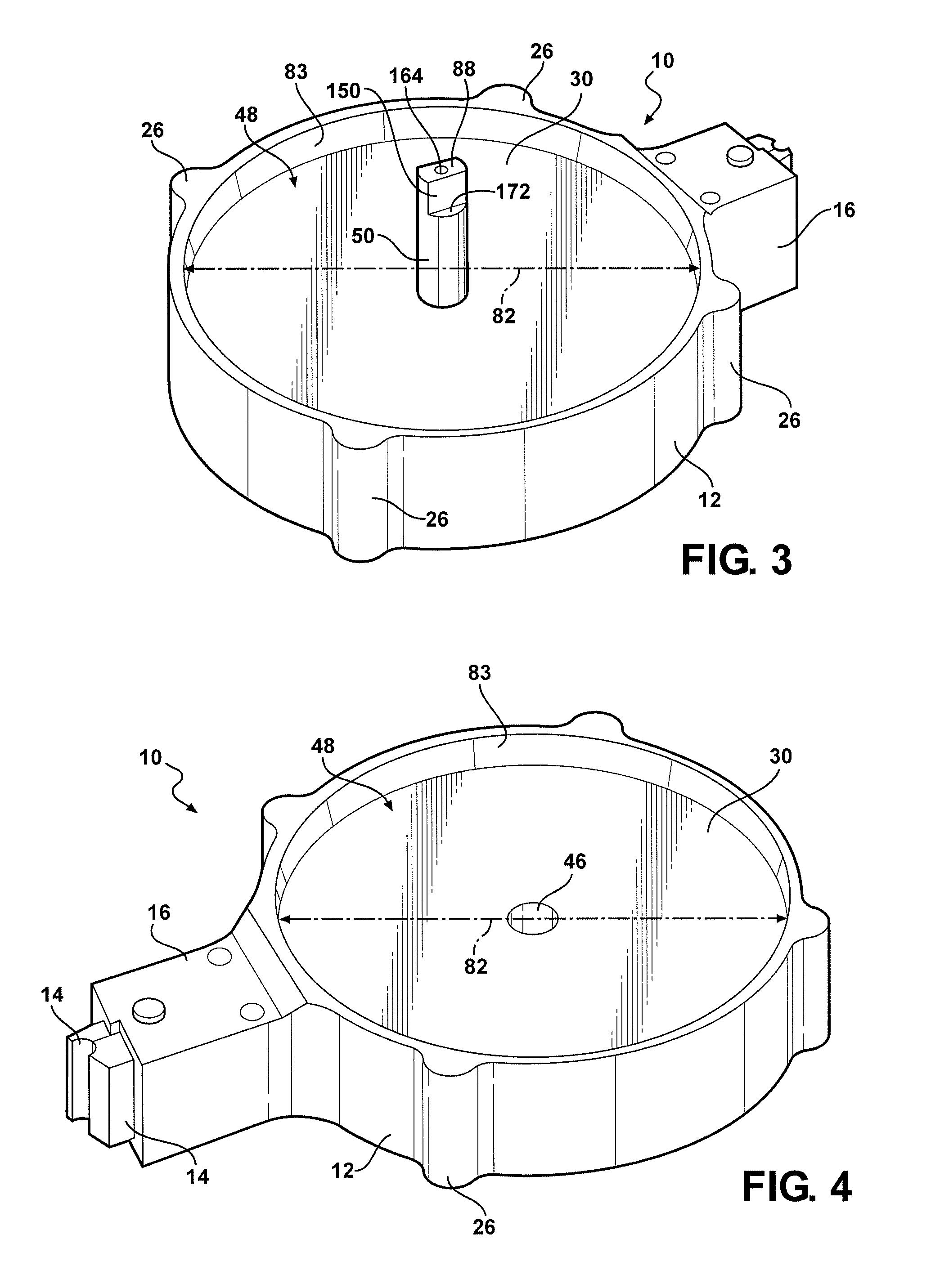
[0091]An ammunition feed system is shown in the Figures according to the present invention, generally at 10. The basic housing or body 12 of the system includes feed lips 14 installed at a neck 16 of the body 12. Also included is a larger opening or pocket, shown generally at 18, in the center of the body 12 which is for the insertion of an encapsulated spring clutch mechanism, generally shown at 20. Also shown in the Figures is a spiral channel 22 which is used to contain a plurality of firearm cartridges, generally shown at 24. On the outside of the body 12 are projections 26 having threaded apertures 27 used to fasten a spiral cover 28 to the housing 12. In alternate embodiments, the projections 26 are of different shapes and forms, depending upon the fasteners used. A firewall 30 (best seen in FIGS. 1-7), separate...


PUM


Abstract

The present invention is a firearm cartridge feeding system to automatically feed firearm cartridges in a successive order one diameter of a firearm cartridge at a time, to the chamber of a bolt action, semi-automatic, or fully automatic firearm until all firearm cartridges in the system are expended. The firearm cartridges are stored in a tight spiral channel side by side to maximize the use of the peripheral space surrounding the area of a magazine well or feed point of a firearm. The housing or body of the firearm feeding system consists of a multiple segment body or housing. The housing contains a spiral channel, clutch mechanism pocket and a spring drive compartment which supports the storage of firearm cartridges and the arrangement of a drive system for feeding the firearm cartridges to the feed lips.

Description

CROSS-REFERENCE TO RELATED APPLICATIONS[0001]This application claims the benefit of U.S. Provisional Application No. 61 / 280,810, filed Nov. 9, 2009. The disclosure of the application is incorporated herein by reference.FIELD OF THE INVENTION[0002]This invention is directly related to firearms, and the feeding of non-linked cartridges in semi-automatic and automatic small arms. More particularly, the invention expands on the capacity of cartridges that can be fed into a firearm without having to change magazines as frequently.BACKGROUND OF THE INVENTION[0003]Since the discovery of gunpowder in the ninth century, and the invention of firearms in the tenth century, firearms have made significant advancements. Single shot, single barreled, muzzle loading flintlock musket firearms of the late 1700's and early 1800's were a great advancement in the history of firearms, but they did not offer the marksman with a quick subsequent shot(s). If the target was missed and the marksman wanted to ...

Claims


Application Information

Patent Timeline
IPC IPC(8): F41A9/75
CPCF41A9/75F41A9/70
Inventor LASICHAK, ANDREA J.QUETSCHKE, THOMAS E.WOODWARD, KENNETH D.
Owner MENINAS
Learn More