Self rechargeable synergy drive for a motor vehicle

a technology for motor vehicles and synergy drives, which is applied in the direction of wind motors with solar radiation, light to electrical conversion, electric devices, etc., can solve the problems of generating electricity slowing the vehicle, the inability to handle the drive power, and the inability to cope with the extra load. , to achieve the effect of saving energy

Inactive Publication Date: 2014-03-20
PENEV KRASSIMIRE MIHAYLOV
View PDF22 Cites 32 Cited by
  • Summary
  • Abstract
  • Description
  • Claims
  • Application Information

AI Technical Summary

Benefits of technology

[0058]Preferably, some of the motor vehicle wheels are also equipped with conventional friction brakes and / or conventional regenerative braking that recoup some of the energy lost during stopping by saving the energy in a storage battery or set of storage batteries to be used later to power the motor whenever the car is in electric mode.

Problems solved by technology

Conversely, lifting slightly on the throttle will decrease current flow to the motor and the vehicle will slow down.
But how does generating electricity slow the vehicle?
Traction motors sized to handle the drive power may not be able to cope with the extra load and the battery may not be able to accept charge at a sufficiently high rate.
However, unlike electro-mechanical brakes, which apply mechanical pressure on two separate objects, eddy current brakes slow an object by creating eddy currents through electromagnetic induction which create resistance, and in turn either heat or electricity.
The braking energy of the vehicle is converted in eddy current losses which lead to a warming of the rail.
Stop-and-go driving can quietly destroy a vehicle's friction brakes, causing it to overshoot a busy intersection.
Because of the tendency of eddy currents to oppose, eddy currents cause energy to be lost.
More accurately, eddy currents transform more useful forms of energy, such as kinetic energy, into heat, which is generally much less useful.
This very property, however, is also one of magnetic breaking's disadvantages in that the eddy force itself can never completely stop a train in ideal condition.
They can only be recovered by remagnetisation.

Method used


Image

  • Self rechargeable synergy drive for a motor vehicle
  • Self rechargeable synergy drive for a motor vehicle
  • Self rechargeable synergy drive for a motor vehicle

Examples


Embodiment Construction

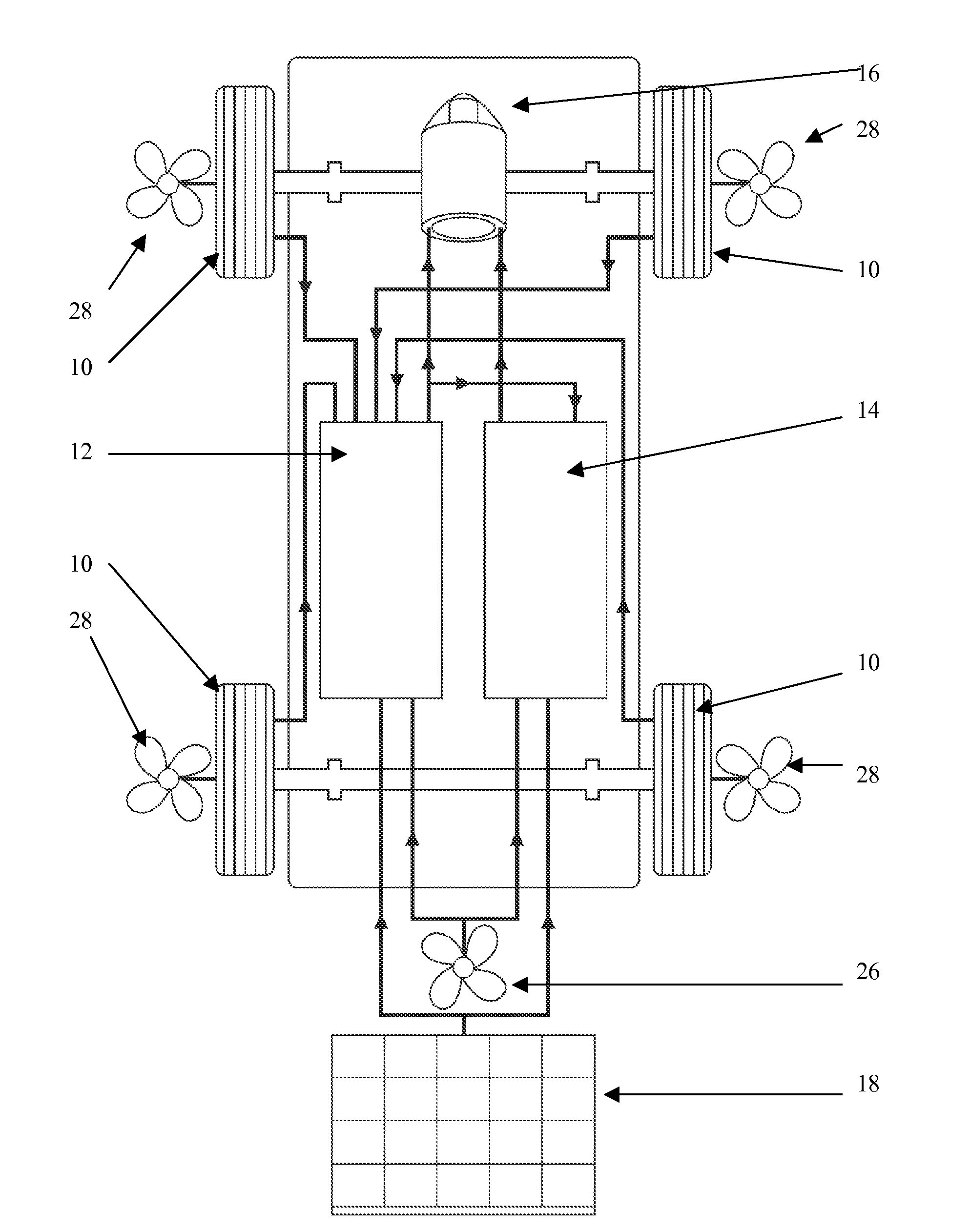
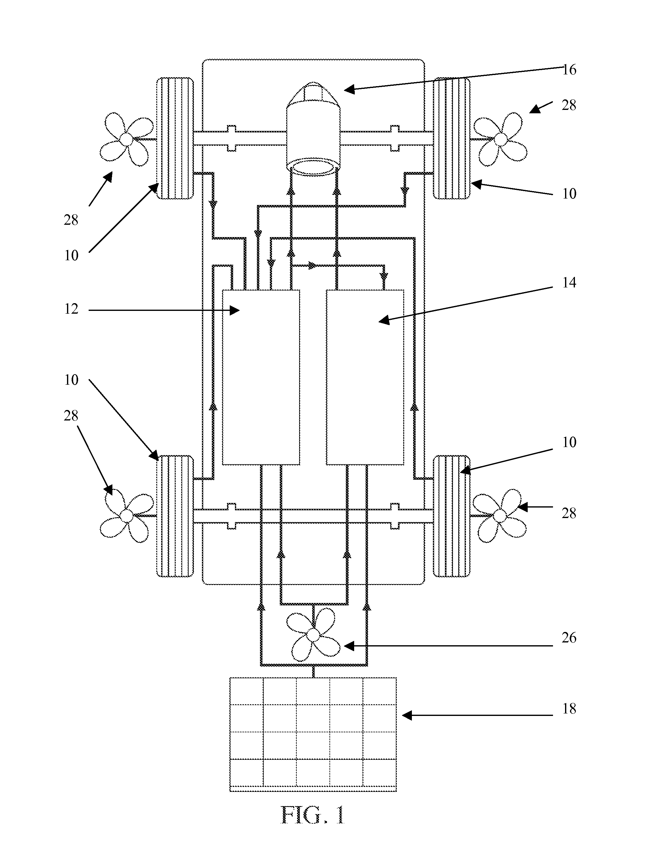
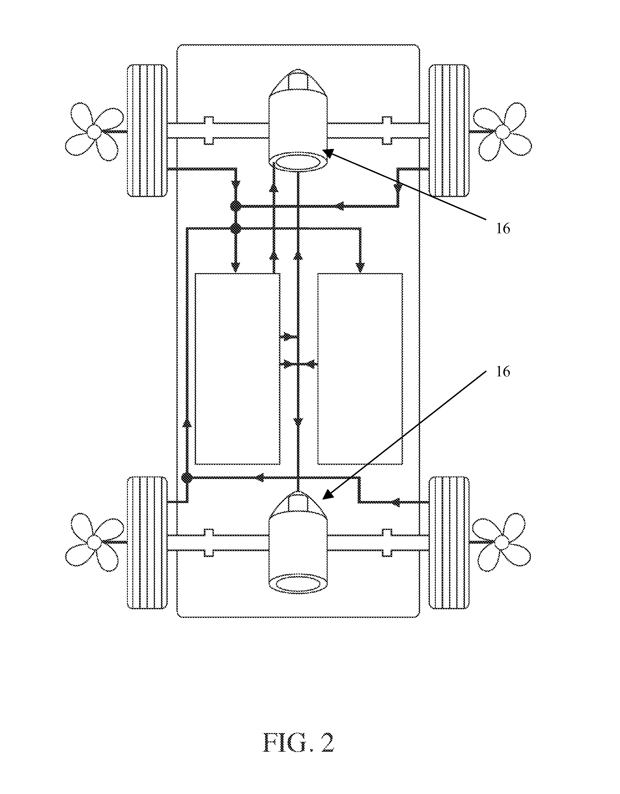
[0070]Turning to the drawing, FIGS. 1-3 show schematically respective drive systems of motor vehicle. FIG. 1 shows a single motor drive system. FIG. 2 shows a dual motor drive system. FIG. 3 shows a four motor drive system with each motor in a respective wheel.

[0071]FIGS. 1-3 have the following components in common: four wheels 10, two storage batteries 12, 14 and at least one motor 16 powered by the batteries 12, 14. While FIGS. 1-3 shows a wind suction fan 28 at each wheel that directs airflow to a turbine generator 26 and FIG. 1 shows a roof mounted solar panel electricity generator 18. The roof mounted solar panel electricity generator 18 and the turbine generator 26 may be provided in the same manner for the embodiments of FIGS. 2 and 3.

[0072]As shown in FIGS. 1-4, each wheel is equipped with induction means 20 for creating a magnetic field in proximity of conductive elements. The relative arrangement may be either that the magnetic field turns within conductive elements or the...


PUM


Abstract

Wheels may be equipped with a stator and rotor to induce current to generate electricity as the wheels rotate or to slow down the wheels in response to the application of a brake of the vehicle. Air may be sucked through the wheels through mesh screens to create air flow that passes through ductwork to reach a turbine generator, which generates electricity in response to blade rotation from air flow. A roof mounted solar energy conversion system may generate electricity. A vehicle power supply boosts its energy from all the electricity generated.

Description

CROSS-REFERENCE TO COPENDING PATENT APPLICATIONS[0001]This is a continuation-in-part of patent application Ser. No. 13 / 476,192 filed May 21, 2012.BACKGROUND OF THE INVENTION[0002]1. Field of the Invention[0003]The present invention relates to boosting an amount of electrical energy available for a motor vehicle from recovered energy sources, including motor vehicle kinetic energy, wind flow, and solar radiation, and providing frictionless braking powered from the recovered energy sources.[0004]2. Discussion of Related Art[0005]The contents of the BACKGROUND OF THE INVENTION for U.S. Ser. No. 13 / 476,192 is incorporated herein by reference, which includes discussions under subheadings entitled: a. vehicle energy source recoveries, b. electric retarders, c. regenerative braking, d. wheel / hub motors, and e. converting kinetic rotary wheel motion into electricity generation.[0006]US patent publication no. 2012 / 0265381 to Lee discloses an electric vehicle having a motor generator, which c...

Claims


Application Information

Patent Timeline
Patent Type & Authority Applications(United States)
IPC IPC(8): B60L7/28B60L8/00
CPCB60L7/28B60L8/006B60L8/003B60L7/10B60L2220/46B60K11/02B60K2001/006B60K2016/006B60L2200/26Y02T10/90Y02E10/728F03D9/32F03D9/25F03D9/007H02S10/12Y02E10/50Y02E10/72Y02T10/7072
Inventor PENEV, KRASSIMIRE MIHAYLOV
Owner PENEV KRASSIMIRE MIHAYLOV
Why Eureka
Try Eureka