Class-f CMOS oscillator

a class-f oscillator and oscillator technology, applied in the field of cmos-based class-f oscillator topology, can solve the problems of deteriorating the equivalent q-factor of the tank, injecting more noise into the tank, etc., and achieves the reduction of the effective noise factor of the oscillator, the effect of improving phase noise performance and reducing the effective impulse sensitivity function (isf)

Inactive Publication Date: 2014-03-20
TECH UNIV DELFT
View PDF7 Cites 35 Cited by
  • Summary
  • Abstract
  • Description
  • Claims
  • Application Information

AI Technical Summary

Benefits of technology

[0007]A novel and useful oscillator topology demonstrating an improved phase noise performance that exploits the time-variant phase noise model with insights into the phase noise conversion mechanisms. The oscillator is based on enforcing a pseudo-square voltage waveform around an LC tank by increasing the third-harmonic of the fundamental oscillation voltage thr

Problems solved by technology

Hence, the transistors provide a discharge path between the output node and ground, thus deteriorating th

Method used


Image

  • Class-f CMOS oscillator
  • Class-f CMOS oscillator
  • Class-f CMOS oscillator

Examples


Embodiment Construction

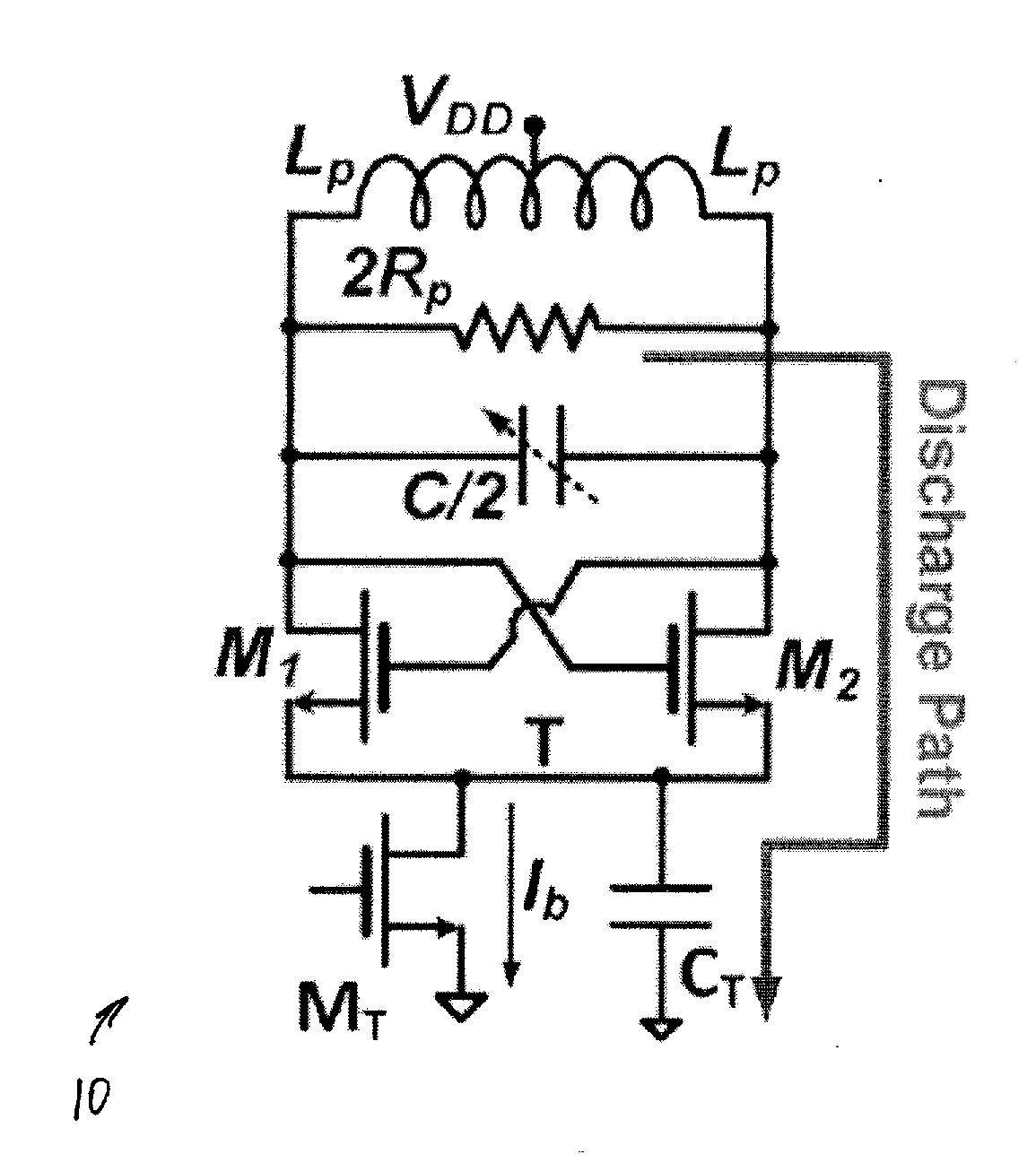
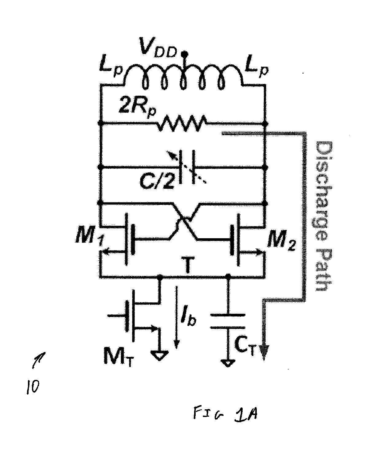
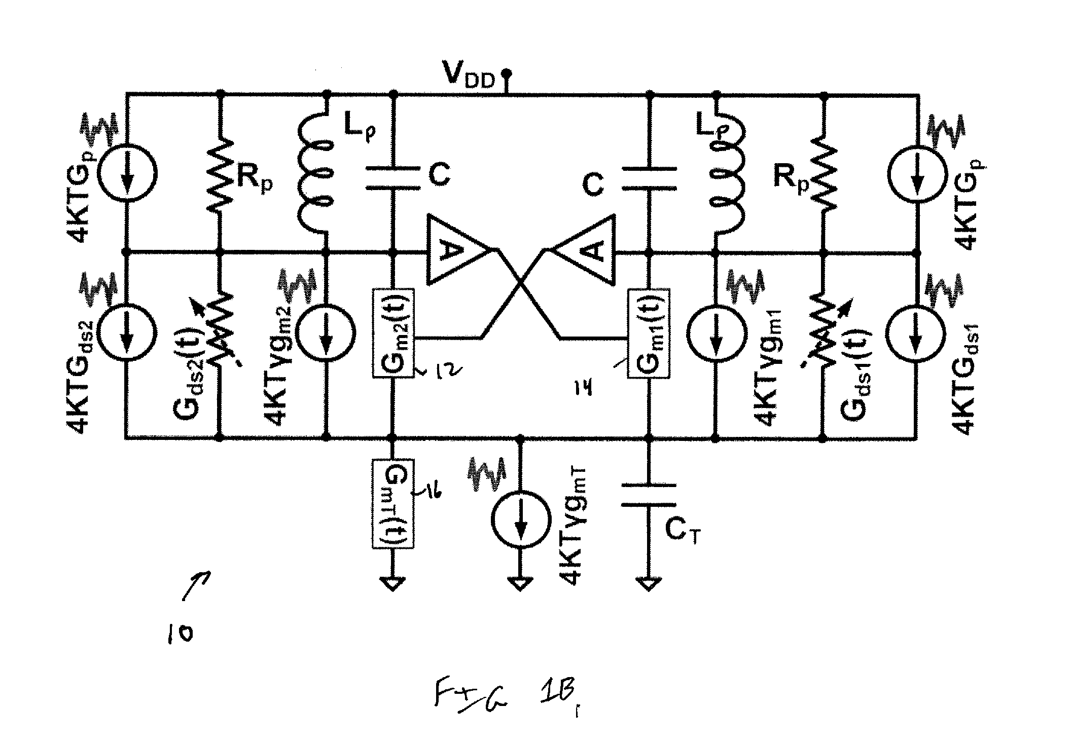
[0056]The present invention is a high spectral purity and high power efficiency RF CMOS oscillator having applications in up / down conversion of desired baseband data to radio frequencies. The oscillator is a vital and essential building block of wireless or wireline communication systems. RF oscillators typically consume disproportionate amounts of power of an RF frequency synthesizer and burn more than 30% of the cellular RX power. The RF oscillator of the present invention exhibits reduced power consumption thereby greatly benefiting the overall transceiver power efficiency and battery lifetime.

[0057]The oscillation waveform of the RF CMOS oscillator of the present invention is pseudo-square across its LC tank rather than sinusoidal. It decreases the circuit-to-phase noise conversion of the oscillators meaning the oscillator exhibits improved power efficiency compared to prior art oscillator structures at the same phase noise performance. This translates directly to longer battery...


PUM


Abstract

A novel and useful oscillator topology demonstrating an improved phase noise performance that exploits the time-variant phase noise model with insights into the phase noise conversion mechanisms. The oscillator is based on enforcing a pseudo-square voltage waveform around an LC tank by increasing the third-harmonic of the fundamental oscillation voltage through an additional impedance peak. Alternatively, the oscillator is based on enforcing clipped oscillation waveform by increasing the second harmonic of the fundamental oscillation voltage through an additional impedance peak. This auxiliary impedance peak is realized by a transformer with moderately coupled resonating windings. As a result, the effective impulse sensitivity function (ISF) decreases thus reducing the oscillator's effective noise factor such that a significant improvement in the oscillator phase noise and power efficiency are achieved.

Description

REFERENCE TO PRIORITY APPLICATION[0001]This application claims priority to U.S. Provisional Application Ser. No. 61 / 701,690, filed Sep. 16, 2012, entitled “Digitally Intensive Transceiver,” U.S. Provisional Application Ser. No. 61 / 701,695, filed Sep. 16, 2012, entitled “Class-F Oscillator,” U.S. Provisional Application Ser. No. 61 / 704,522, filed Sep. 23, 2012, entitled “RF Transceiver,” and U.S. Provisional Application Ser. No. 61 / 829,976, filed May 31, 2013, entitled “Time Domain RF Signal Processing,” all of which are incorporated herein by reference in their entirety.FIELD OF THE INVENTION[0002]The present invention relates to the field of semiconductor integrated circuits, and more particularly relates to a CMOS based class-F oscillator topology.BACKGROUND OF THE INVENTION[0003]Designing voltage-controlled and digitally-controlled oscillators (VCO, DCO) of high spectral purity and low power consumption is quite challenging, especially for a GSM transmitter (TX), where the oscill...

Claims


Application Information

Patent Timeline
IPC IPC(8): H03B7/06
CPCH03B7/06H03B5/1228H03B5/1296H03B5/1215H03B5/124H03L7/099H03B5/1218H03B1/00H04B1/10H04B1/26H03H19/002H03L7/00
Inventor BABAIE, MASOUDSTASZEWSKI, ROBERT BOGDAN
Owner TECH UNIV DELFT
Why Eureka
Try Eureka