Radiation generating unit, radiation imaging system and target

a radiation generation unit and radiation imaging technology, applied in the direction of x-ray tubes, material analysis using wave/particle radiation, instruments, etc., can solve the problems of high speed switching, high vacuum, and uncertainty about the reliability of movable mechanisms in high vacuum and maintenance of vacuum air tightness, so as to achieve high-quality images and suppress the deviation of radiation focus

Inactive Publication Date: 2014-03-27
CANON KK
View PDF1 Cites 19 Cited by
  • Summary
  • Abstract
  • Description
  • Claims
  • Application Information

AI Technical Summary

Benefits of technology

[0010]It is an object of the present invention to suppress a deviation in radiation focus caused by switching the radiation qualities, while allowing the radiation qualities of high energy radiations to be distinctly varied so as to enable a highly accurate image to be acquired by dual-energy imaging.

Problems solved by technology

However, high speed switching is difficult.
Accordingly, uncertainty remains about reliability of movable mechanisms in a high vacuum and maintenance of vacuum airtightness.
Unfortunately, if the path of the electron beam is changed to vary a position to be irradiated with the electron beam, a deviation occurs in positional relationship between the center (radiation focus) of a radiation generating position and an object.
Accordingly, errors occur in operation on pieces of projection data with respect to each other, and weighted addition and subtraction processes on reconstructed images with respect to each other.
As a result, there are problems in that accuracy of a generated image is degraded, for instance, the contours of the acquired image become hazy.

Method used


Image

  • Radiation generating unit, radiation imaging system and target
  • Radiation generating unit, radiation imaging system and target
  • Radiation generating unit, radiation imaging system and target

Examples


first embodiment

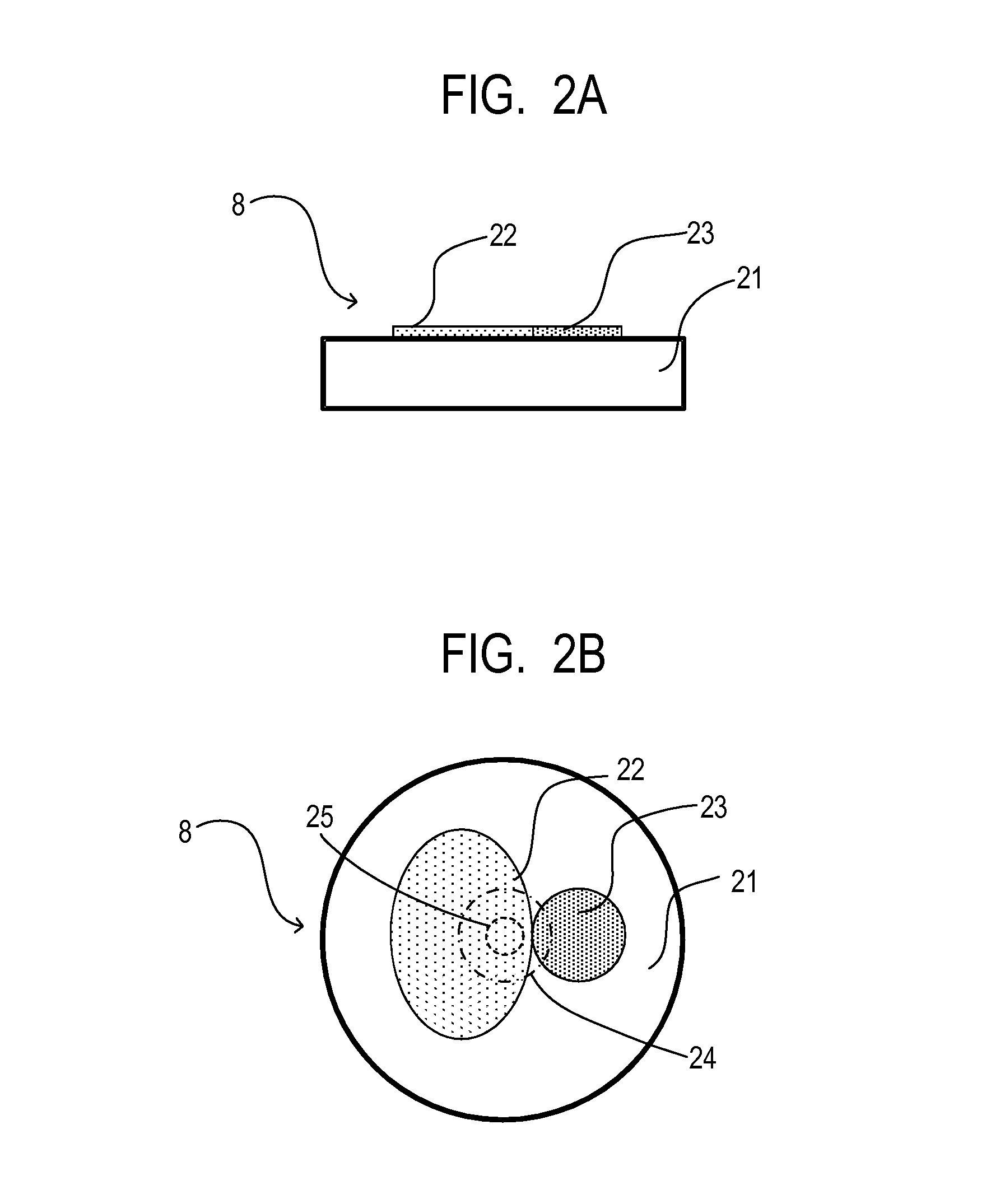
[0034]As illustrated in FIGS. 2A and 2B, the target 8 is designed such that multiple types of target layers formed of different materials, i.e., a first target layer 22 and a second target layer 23, are formed on a surface of the substrate 21. The substrate 21 can be desirably formed of diamond, beryllium, and carbon that do not affect occurring radiations.

[0035]The constituent materials of the first and second target layers 22 and 23 may be any of tungsten, molybdenum, rhodium, tantalum, and niobium that have a high atomic number and a high melting point, and alloys thereof with another element material. Selection and combination of materials having atomic numbers apart by at least two can largely change the resulting energy distribution. Accordingly, although the first and second target layers 22 and 23 may be made of combination of elements having adjacent atomic numbers, the layers may desirably be combination of metals having atomic numbers apart by at least two or combination ...

second embodiment

[0038]FIGS. 3A and 3B illustrate a target 8 of a second embodiment. A first target layer 31 and a second target layer 32 are provided in the same thickness on an identical surface of a substrate 21 in a concentric circular manner relative to the center of the region to be irradiated with an electron beam. Reference numeral 24 illustrates a circumferential line of the region to be irradiated with an electron beam enlarged in diameter, and reference numeral 25 illustrates a circumferential line of the region to be irradiated with an electron beam narrowed in diameter. According to this configuration, when the electron beam is narrowed in diameter, a radiation is generated only from the first target layer 31. In contrast, when the electron beam is enlarged in diameter, a radiation having composite energy characteristics of the first target layer 31 and the second target layer 32 is emitted point-symmetrically with respect to the center of the region to be irradiated with the electron b...

third embodiment

[0039]FIGS. 4A and 4B illustrate a target 8 of a third embodiment. A first target layer 41 and a second target layer 42 are provided in the same thickness on an identical surface of a substrate 21 in a concentric circular manner relative to the center of the region to be irradiated with an electron beam. In addition, a third target layer 43 is further arranged in the same thickness in a concentric circular manner relative to the center of the region to be irradiated with an electron beam. According to this configuration, change in diameter of the electron beam can arbitrarily select from among three types that include a radiation only from the first target layer 41, a radiation having composite energy characteristics of the first target layer 41 and the second target layer 42, and a radiation having composite energy characteristics of the first target layer 41, the second target layer 42 and the third target layer 43. Each of the radiations having the composite energy characteristic...


PUM

PropertyMeasurementUnit
energyaaaaaaaaaa
atomic numbersaaaaaaaaaa

Abstract

A radiation generating unit of the present invention includes an electron beam source that emits an electron beam and can change the size of a region to be irradiated with the electron beam on a target while maintaining constant the center position of the region to be irradiated with the electron beam. Furthermore, a target is adopted where the number of types of target layers included in the region to be irradiated with the electron beam can be changed by changing the size of the region to be irradiated with the electron beam. The radiation quality can be switched without changing the radiation focus, and the radiation quality of a high energy radiation can be largely changed.

Description

BACKGROUND OF THE INVENTION[0001]1. Field of the Invention[0002]The present invention relates to a target that generates a radiation by being irradiated with an electron beam, a radiation generating unit including the target, and a radiation imaging system including the radiation generating unit.[0003]2. Description of the Related Art[0004]In the medical field, diagnostic imaging that uses dual-energy imaging has been known as one method among X-ray imaging methods of more clearly observing an affected area. The dual-energy imaging uses two types of X-rays with different energy distributions (radiation quality). As target layers, for instance, a radiation generating target (hereinafter, called a target) on which tungsten having a high atomic number is formed into a film, and a target on which molybdenum having a low atomic number is formed into a film are adopted. Both the targets are switched, an object is irradiated with X-rays, and projection data by X-rays from each target is co...

Claims


Application Information

Patent Timeline
Patent Type & Authority Applications(United States)
IPC IPC(8): H01J35/08G01N23/04
CPCG01N23/04H01J35/08H01J35/24H01J35/32H01J35/116
Inventor YAMADA, SHUJITSUKAMOTO, TAKEOYOSHITAKE, TADAYUKINOMURA, KAZUSHI
Owner CANON KK
Why Eureka
Try Eureka