Radiographic image detecting device and control method thereof

a detecting device and radiographic image technology, applied in diagnostics, medical science, television systems, etc., can solve the problems of long detection time, low detection accuracy, high susceptibility to noise, etc., and achieve the effect of increasing the accuracy of synchronization control, small size, and large siz

Active Publication Date: 2014-03-27
FUJIFILM CORP
View PDF3 Cites 32 Cited by
  • Summary
  • Abstract
  • Description
  • Claims
  • Application Information

AI Technical Summary

Benefits of technology

[0014]An object of the present invention is to provide a radiographic image detecting device that can perform an accurate synchronization control with timing of the start of radiation emission and an accurate automatic exposure control for controlling a total radiation irradiation amount, and a control method of the radiographic image detecting device.
[0028]According to the present invention, the first detection area used in the synchronization control is relatively large in size, while the second detection area used in the automatic exposure control is relatively small in size. The larger the first detection area, the likelier it becomes that the first detection area includes a directly exposed area, which is not opposed to the object. Performing the synchronization control based on the detection signal of the directly exposed area allows increase in the accuracy of the synchronization control. On the other hand, since the automatic exposure control uses the second detection area, which is a part of the first detection area used in the synchronization control and smaller than the first detection area, the directly exposed area tends to be excluded from the second detection area. Performing the automatic exposure control based on the detection signal of the area opposed to the object allows increase in the accuracy of the automatic exposure control. Therefore, according to the present invention, it is possible to provide the radiographic image detecting device that can perform the accurate synchronization control with timing of the start of radiation emission and the accurate automatic exposure control for controlling the total radiation irradiation amount, and the control method of the radiographic image detecting device.

Problems solved by technology

Thus, using the area opposed to the object as the detection area requires longer detection time, as compared with the case of using the directly exposed area as the detection area.
This also causes high susceptibility to noise because of a low output value of a signal in accordance with the low X-ray irradiation amount, and low detection accuracy.
This results in underexposure of the X-ray image.

Method used


Image

  • Radiographic image detecting device and control method thereof
  • Radiographic image detecting device and control method thereof
  • Radiographic image detecting device and control method thereof

Examples


first embodiment

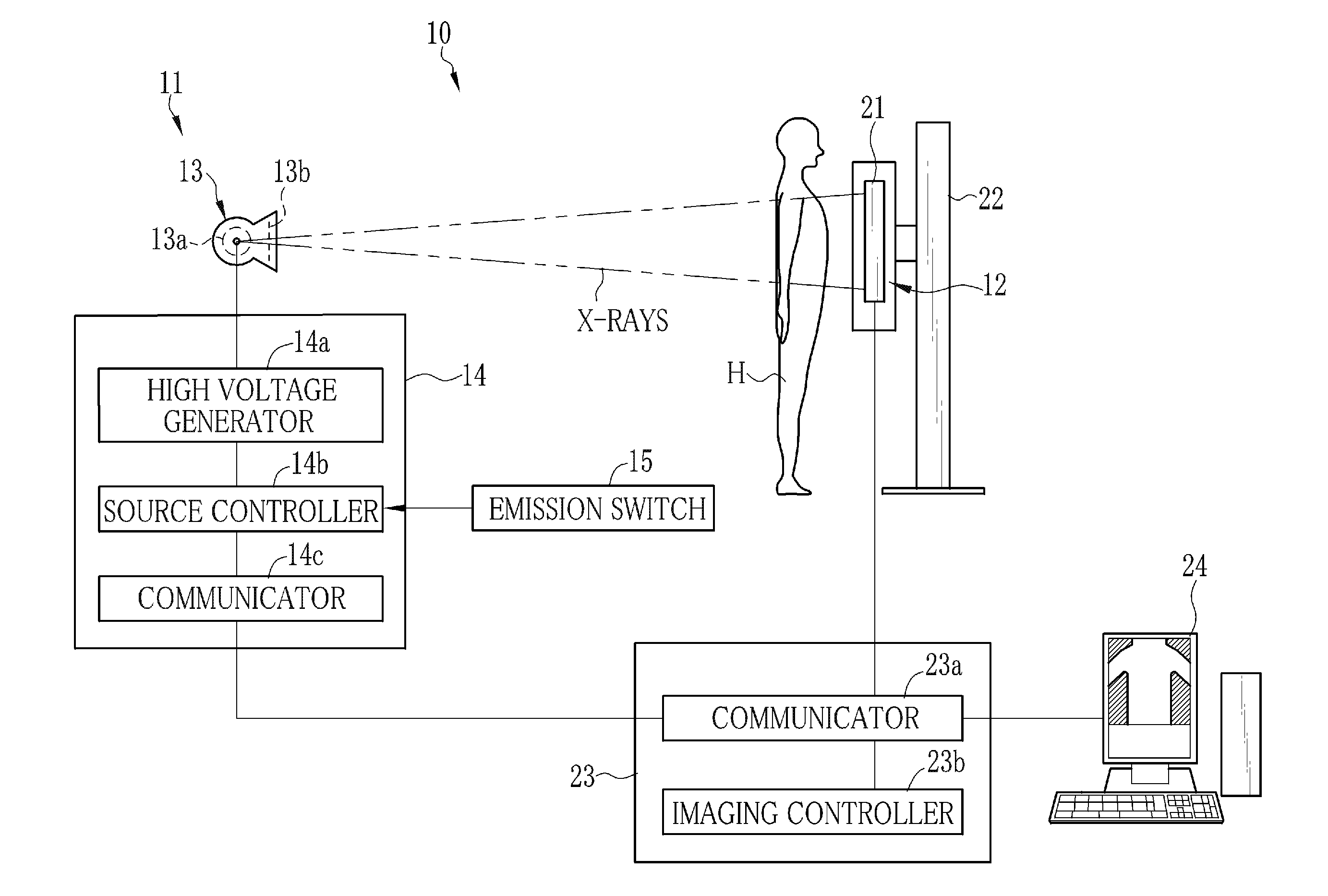
[0042]In FIG. 1, an X-ray image capturing system 10 is constituted of an X-ray generating apparatus 11 and an X-ray imaging apparatus 12. The X-ray generating apparatus 11 includes an X-ray source 13, a source control unit 14 for controlling the X-ray source 13, and an emission switch 15. The X-ray source 13 has an X-ray tube 13a for emitting X-rays, and an irradiation field limiter (collimator) 13b for limiting an irradiation field of the X-rays radiating from the X-ray tube 13a.

[0043]The X-ray tube 13a has a cathode made of a filament for emitting thermoelectrons, and an anode (target) for radiating the X-rays by collision of the thermoelectrons emitted from the cathode. The irradiation field limiter 13b has, for example, four lead plates for blocking the X-rays. The four lead plates form a rectangular irradiation opening for transmitting the X-rays therethrough. Shifting the positions of the lead plates varies the size of the irradiation opening and restricts an irradiation fiel...

second embodiment

[0103]The first embodiment is described with taking the capture of a still image as an example, but the present invention is applicable to the case of capturing a moving image, such as fluoroscopy. In capturing the moving image, as shown in FIG. 10, for example, the X-rays are continuously applied in pulses and one frame, which is an image composing part of the moving image, is obtained from each X-ray pulse. In this case, all the divided sections A to I are used as the first detection area in the synchronization control. The start of emission of each of the X-ray pulses applied continuously is detected based on the output voltages Vout of the short pixels 62a to 62i in the first detection area. In synchronization with the start of emission, the FPD 36 is shifted from the ready state to the accumulation operation. After that, the automatic exposure control is performed during the application of each X-ray pulse. In the automatic exposure control, the divided section that is opposed ...

third embodiment

[0106]The short pixels are used as the radiation detectors in each of the above embodiments, but a plurality of photosensor arrays 71, each having a plurality of photodiodes arranged in a matrix, may be used instead of the short pixels as shown in an FPD 70 of FIG. 11. The photosensor array 71 is stacked on a detection panel 72, which is similar to the detection panel 30 of the first embodiment. The detection panel 72 is different from the detection panel 30 in terms of providing no short pixel, but the other structure thereof is the same as that of the detection panel 30. The photosensor array 71 is preferably made of OPC (organic photoelectric conversion material), for example. The OPC can be formed extremely thin and hardly absorbs the X-rays. Therefore, there is a merit that if the OPC is disposed on an X-ray irradiation side relative to the imaging area in the detection panel 72, the disposition of the OPC hardly affects X-ray image quality.

[0107]The radiation detectors exist i...


PUM


Abstract

An X-ray image detecting device has an FPD having a matrix of pixels each for accumulating signal charge in accordance with an X-ray irradiation amount. An imaging area of the FPD is partitioned into a plurality of divided sections A to I. Each of the divided sections A to I has a short pixel for detecting X-ray irradiation. In a synchronization control for controlling the FPD in synchronization with detection of a start of X-ray emission from an X-ray source, a control unit for controlling the X-ray image detecting device uses all the divided sections A to I. In an automatic exposure control for stopping the X-ray emission from the X-ray source by detecting a total X-ray irradiation amount, the control unit uses part of the divided sections, e.g. the short pixels of the divided sections that are judged to be opposed to an object in the synchronization control.

Description

BACKGROUND OF THE INVENTION[0001]1. Field of the Invention[0002]The present invention relates to a radiographic image detecting device for detecting a radiographic image of an object and a control method thereof.[0003]2. Description Related to the Prior Art[0004]In a medical field, for example, an X-ray image capturing system using X-rays as a kind of radiation is known. The X-ray image capturing system is constituted of an X-ray generating device having an X-ray source for emitting the X-rays, and an X-ray image detecting device for detecting an X-ray image, which represents image information of an object, by receiving application of the X-rays that have been emitted from the X-ray source and transmitted through the object. The X-ray source is provided with a tube current for determining an X-ray dose per unit of time and a tube voltage for determining X-ray quality (energy spectrum), as an imaging condition. The imaging condition is determined whenever imaging is performed, in acc...

Claims


Application Information

Patent Timeline
Patent Type & Authority Applications(United States)
IPC IPC(8): A61B6/00
CPCA61B6/542A61B6/4233A61B6/4283H04N5/32H04N23/71H04N25/53H04N25/76
Inventor OHTA, YASUNORIKITANO, KOUICHINISHINO, NAOYUKINAKATSUGAWA, HARUYASUIWAKIRI, NAOTO
Owner FUJIFILM CORP
Why Eureka
Try Eureka