Fuel cell system

a fuel cell and system technology, applied in the direction of battery/fuel cell control arrangement, electrochemical generators, battery/cell propulsion, etc., can solve the problems that the over-discharge of batteries or the lowering of drivability cannot be avoided in some cases, and achieve the effect of lowering drivability

Active Publication Date: 2014-03-27
NISSAN MOTOR CO LTD
View PDF5 Cites 13 Cited by
  • Summary
  • Abstract
  • Description
  • Claims
  • Application Information

AI Technical Summary

Benefits of technology

[0007]An object of the present invention is, therefore, to provide a fuel cell system that is allowed to avoid without fail over-discharge of battery or lowering in drivability upon recovery from idle-stop.

Problems solved by technology

Consequently, depending on the magnitude of requested electric power, over-discharge of battery or lowering in drivability cannot be avoided in some cases.

Method used


Image

  • Fuel cell system
  • Fuel cell system
  • Fuel cell system

Examples


first embodiment

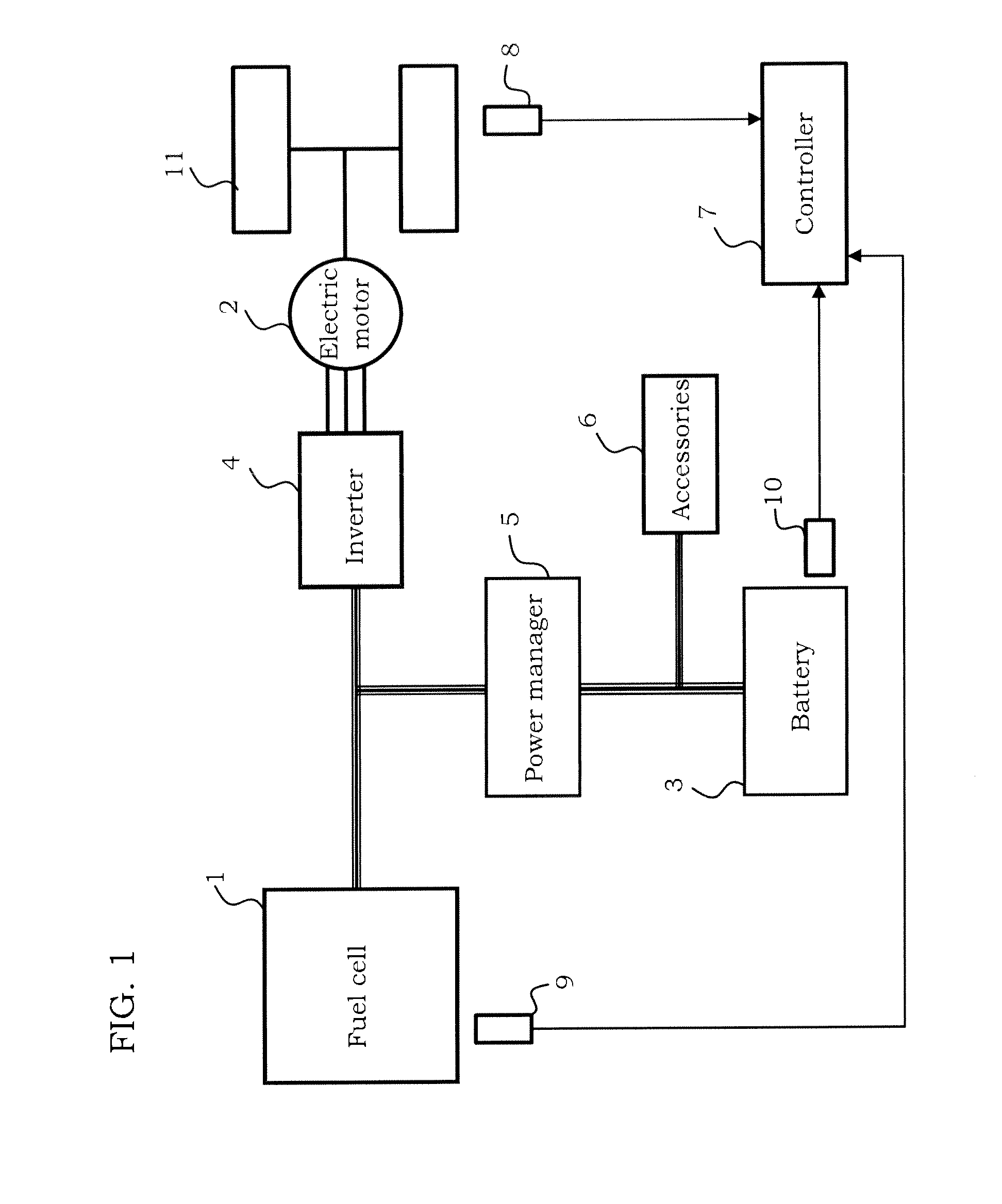
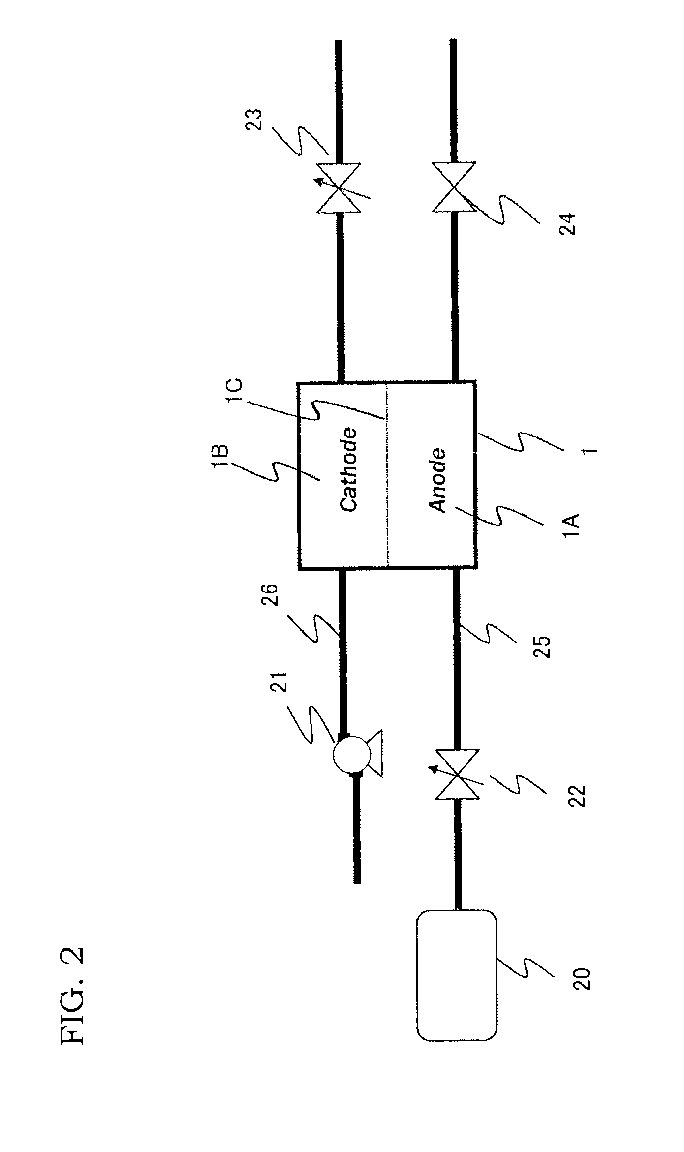
[0032]FIG. 1 is a block diagram illustrating an electric power supply system for vehicles, to which a first embodiment is applied. FIG. 2 is a diagram illustrating an example of a fuel cell system.

[0033]An electric power supply system comprises: a fuel cell stack 1; an electric motor 2 as a load; a battery 3; accessories 6; and a power manager 5 that controls a voltage among the fuel cell stack 1, the electric motor 2, the battery 3, and the accessories 6.

[0034]The fuel cell stack 1 is a direct-current power source, as is shown in FIG. 2, having a structure of piling-up a plurality of unit cells in which a electrolyte membrane 1C is sandwiched between an anode 1A and a cathode 1B. Note that, in FIG. 2, only a unit cell is shown.

[0035]To the anode 1A, through a hydrogen supply passage 25, hydrogen gas that serves as a fuel is supplied. To the cathode 1B, through an air supply passage 26, the air that serves as an oxidant gas is supplied.

[0036]In the hydrogen supply passage 25, a pres...

second embodiment

[0074]The system construction of a second embodiment is basically similar to that of the first embodiment. However, a difference resides in the aspect how the controller 7 reads, as the state quantities of the battery 3, battery temperature and battery deterioration coefficient in addition to the charged electricity of the battery. The battery temperature is detected by a battery temperature sensor. The battery deterioration coefficient is computed by the controller 7. The battery deterioration coefficient is based on a battery property deterioration as the repeating number of charging increases; and this coefficient becomes larger as the deterioration advances. The battery deterioration coefficient is computed, for example, as following: the repeating number of charging is counted; and a preliminarily prepared map that provides a relation between the repeating number of charging and the level of deterioration is retrieved with the said counted number of charging. Of course, the oth...

third embodiment

[0094]The system construction of a third embodiment is basically similar to that of the first embodiment. However, a difference from the first embodiment resides in the computation contents of the stack output-response request computed by the controller 7. In this embodiment, the stack output-response request is computed in accordance with a constant of the power-plant that includes therein the fuel cell stack 1, the power manager 5 and the compressor 21. Note that, the controller 7 computes higher, similarly to the first embodiment and the second embodiment, the lower limit of the stack setup-voltage during idle-stop as the stack output-response request is higher. In addition, the constant at the time of the power-plant response is called as a power-plant output-response performance in the following explanation.

[0095]As the power-plant output-response performance lowers, a time, which is required until the output of the electric motor 2 attains a target output that is determined by...


PUM

PropertyMeasurementUnit
electric poweraaaaaaaaaa
stack voltageaaaaaaaaaa
voltageaaaaaaaaaa

Abstract

The fuel cell system of the present invention comprises: an electric motor, a fuel cell stack, a fuel supply unit, and a controller that controls a power-plant including the fuel cell stack and the fuel supply unit. The controller comprises further: a stack output-response request computing unit to compute a stack output-response request requested for the fuel cell stack; a stack voltage setup unit during idle-stop to set up a lower limit of stack setup-voltage during idle-stop that is set up as a stack voltage during execution of idle-stop so as to be higher as the stack output-response request is larger, and so as to be lower as the request is smaller; and an operation unit of recovering a stack voltage during idle-stop to execute a recovery operation when an actual stack voltage becomes, during execution of idle-stop, lower than the lower limit of stack setup-voltage during idle-stop.

Description

TECHNICAL FIELD[0001]The present invention relates to stack voltage control during idle-stop of a fuel cell system.BACKGROUND ART[0002]In a vehicle or the like which runs with electric power generated by a fuel cell system, electric power generation by the fuel cell is stopped under a running condition of relatively low load or the like. That is, so-called idle-stop is executed in some cases. During idle-stop, air supply to a cathode is stopped. Oxygen that remains in the cathode is consumed by reacting with hydrogen that permeates to the cathode, whereby a stack total-voltage gradually lowers.[0003]Idle-stop is terminated when a charged amount of batteries lowers below a predetermined threshold value or when load is increased by speed-up request or the like. However, it requires time from an instant when fuel supply is re-started to an instant when current is ready to be taken out. In addition, because of electric motor characters, even with the same accelerator operations, a respo...

Claims


Application Information

Patent Timeline
Patent Type & Authority Applications(United States)
IPC IPC(8): H01M8/04
CPCH01M8/04753H01M8/04223B60L58/12B60L58/16B60L58/33B60L58/40B60L50/51B60L58/14B60L1/003H01M8/04619H01M8/0488H01M8/0494H01M16/006B60L2240/12B60L2240/36B60L2240/423B60L2240/549B60L2240/547B60L2240/545B60L2270/145B60L2270/142H01M8/04358H01M8/0438H01M2250/20Y02T10/64Y02T10/70Y02T90/40Y02E60/50Y02E60/10H01M8/04228H01M8/04303H01M8/04225
Inventor KUMADA, MITSUNORIMAKINO, SHINICHIASAI, YOSHITOMO
Owner NISSAN MOTOR CO LTD
Why Eureka
Try Eureka