Hydraulic regeneration apparatus

a technology of energy regeneration and apparatus, applied in mechanical apparatus, transportation and packaging, jet propulsion mounting, etc., can solve the problems of slow vehicle, difficult optimization of energy recovery through discrete components, and faster fuel consumption of trucks, so as to maximize fuel economy and reduce energy

Inactive Publication Date: 2014-03-27
LIGHTNING HYBRIDS
View PDF7 Cites 13 Cited by
  • Summary
  • Abstract
  • Description
  • Claims
  • Application Information

AI Technical Summary

Benefits of technology

[0014]Benefits and advantages of embodiments of the present invention include, but are not limited to, providing an apparatus and method for recovering, storing, and reapplying the kinetic energy of a moving vehicle in such a way that the prime mover of the vehicle uses less energy to accelerate the vehicle, while operating at the maximum possible efficiency over the entire range of required energy recovery rates, maximizing fuel economy, and satisfying performance constraints, such as braking and acceleration performance.

Problems solved by technology

Although work on improved fuel economy has expanded in recent years for all classes of vehicles with the increasing cost of fuel and energy in general, fuel consumed by trucks has been growing at a faster rate than that for passenger cars, perhaps due to the more limited availability of such technology since many trucks already use efficient diesel engines, and the weight constraints associated with these vehicles.
Typical braking systems readily turn the energy of vehicle motion into heat by means friction which slows the vehicle.
Thus, the optimization of energy recovery through discrete components becomes difficult and upper limits to the amount of energy that can be recovered are quickly realized.
Mechanical and hydraulic recovery systems are also plagued by their discrete nature, and optimization is difficult.
That is, as an energy storage device, a hydraulic accumulator has the ability to accept high rates and high frequencies of charging / discharging, both of which as stated are not favorable for batteries.
However, small variations from those specific recovery rates may affect the recovery efficiency; for example, at certain displacements the pump and motor can be efficient volumetrically and mechanically, but small deviations from those conditions may cause heat generation inside of the pump and fluid loss at the low-to-high pressure interface.

Method used


Image

  • Hydraulic regeneration apparatus
  • Hydraulic regeneration apparatus
  • Hydraulic regeneration apparatus

Examples


example 1

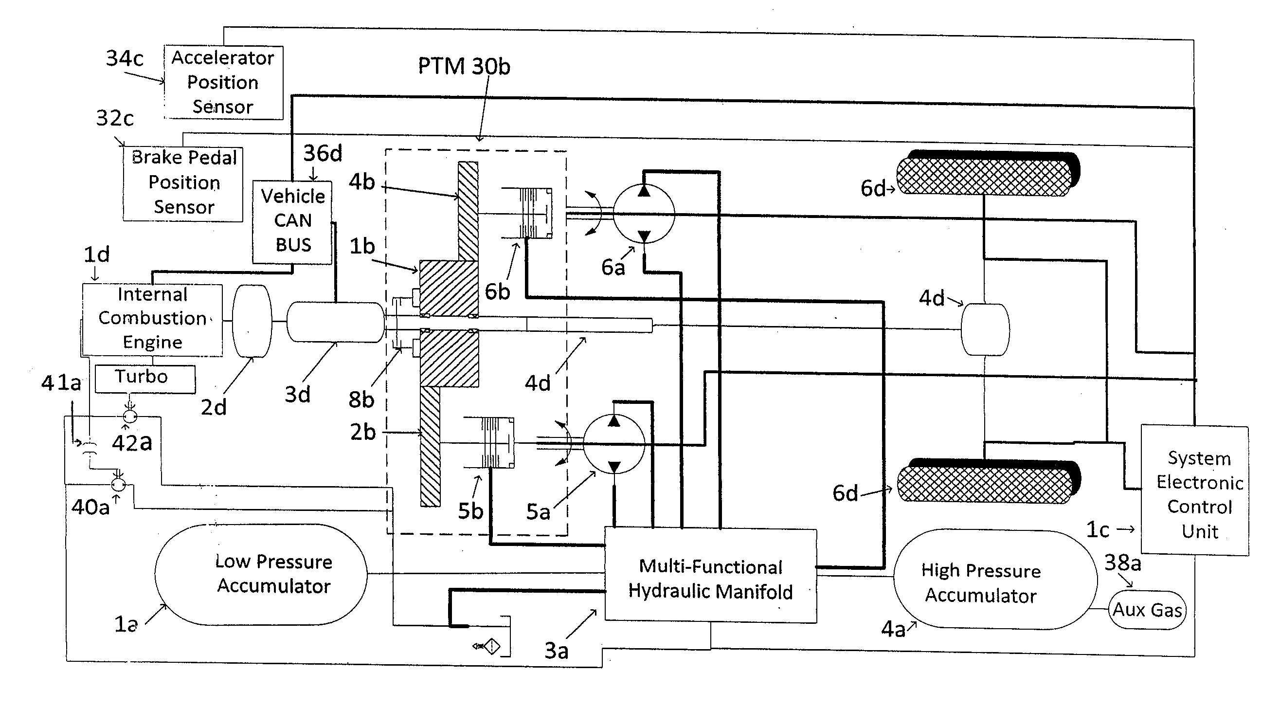
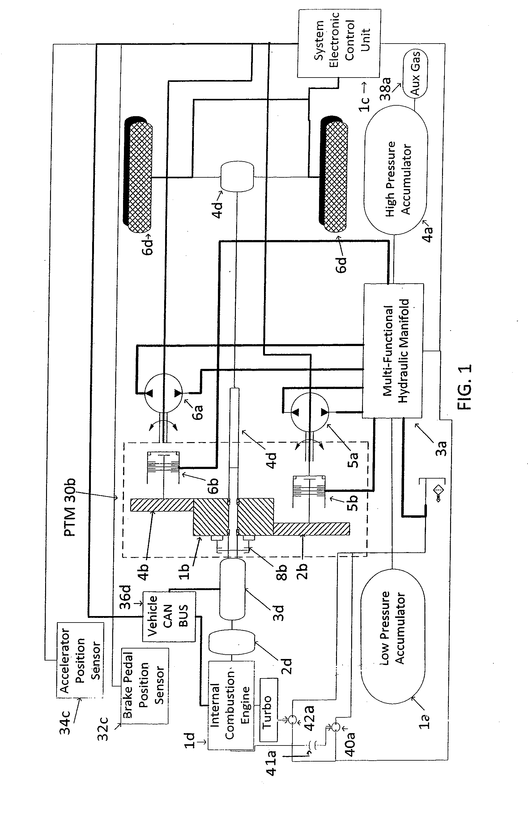
[0049]Embodiments of the present invention may operate in one of three modes. In the first mode, the hydraulic components of the system are completely decoupled from the existing driveline through hydraulically activated clutches 5b and 6b. In this mode the only components in the system that are active are sun gear 1b and the two planetary gears 2b and 4b. In the configuration shown, any time that the drive shaft 4d is rotating, sun gear 1b and planet gears 2b and 4b will also rotate. If included, the high torque, dog-clutch 8b decouples the mechanical components of the system from the existing drive-line in the event of a failure or in instances where long over the road travel is required without stops and starts which limits the effectiveness of the present invention. The mode in which only the sun gear and planet gears are turning is referred to as hydraulic idle mode. If clutches 5b and 6b are engaged, the hydraulic pump / motors 5a and 6a will be rotating as well. Further, if the...

example 2

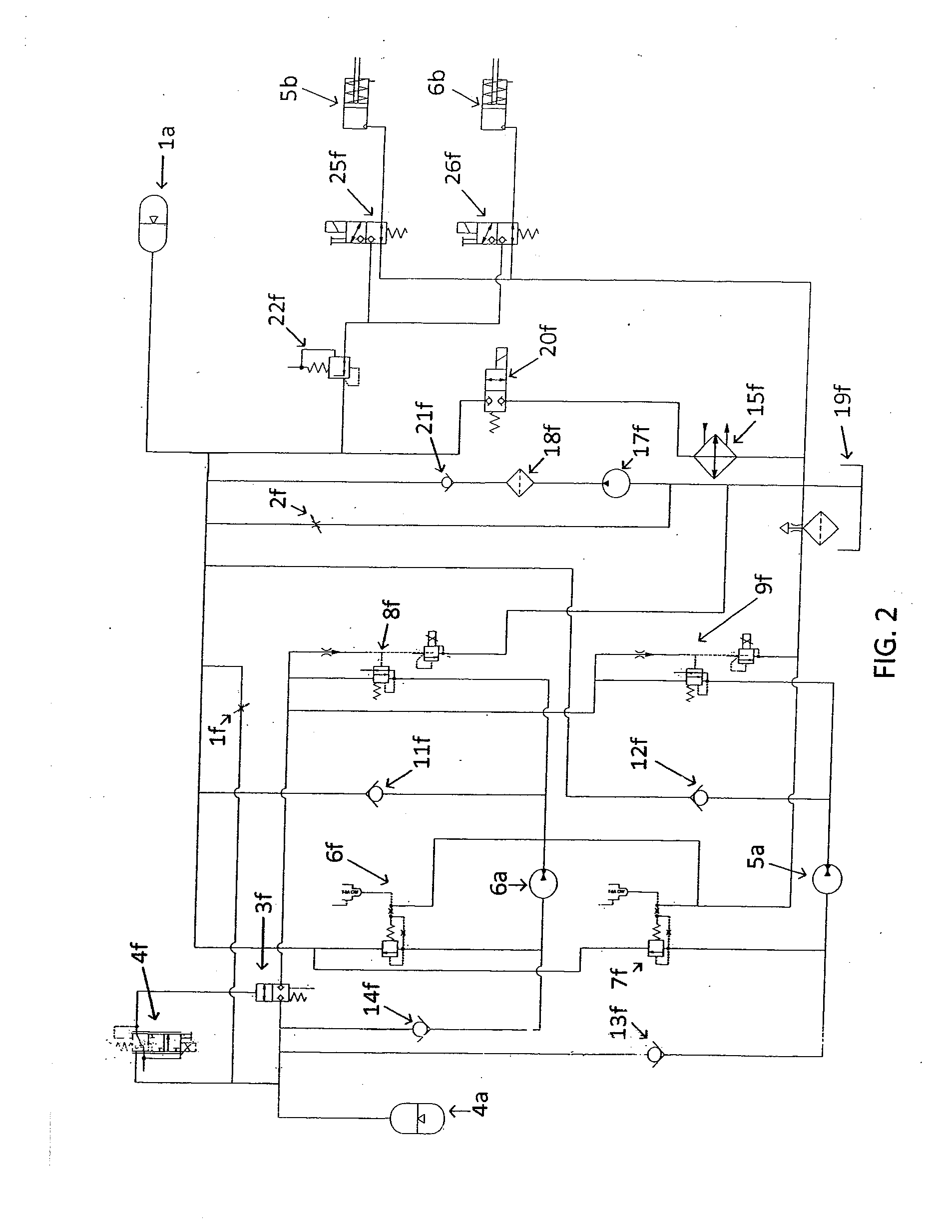
[0050]The second mode, referred to as the braking mode, occurs when one pump / motor unit or some combination of all of the pump / motor units absorbs power transferred from wheels 6d through differential 5d through driveshaft 4d to sun gear 1b. When a driver depresses the brake pedal, the system's electronic control unit 1c measures the brake pedal position and determines how much deceleration the driver is requesting. That deceleration value is converted to a desired torque value calculated by measuring the difference in pressure between low pressure accumulator 1a and high pressure accumulator 4a. Control system 1c then determines which pump / motor 5a or 6a through its fixed mechanical gear ratio or which combination of pumps / motors 5a and / or 6a through their respective mechanical gear ratios, will provide approximately the negative braking torque that the driver is requesting. Once the appropriate selection has been made, the system's electronic control unit 1c commands multi-functio...

example 3

[0055]The third system mode is the motoring mode, where the fluid flows from high-pressure accumulator 4a to low pressure accumulator 1a and applies positive accelerating torque to the vehicle drive-shaft. By introducing high-pressure fluid to the inlets of the pump / motor units, the units produce torque which is transferred from pump / motor units 5a and / or 6a through hydraulically actuated clutches 5b and / or 6b to planet gears 2b and 4b, respectively, to sun gear 1b through driveshaft 4d to differential 5d, and finally to wheels 6d. In this mode of operation, system electronic control unit 1c again monitors the fluid pressure difference between high-pressure accumulator 4a of FIG. 1 and low-pressure accumulator 1a of FIG. 1. Control system 1c calculates the amount of available energy from the pressure difference between the high- and low-pressure accumulators, and which pump / motor combination may be used to meet the driver's demand. In this mode, control system 1c continuously monito...


PUM


Abstract

A hydraulic motor/pump regenerator system for recovering energy from the moving vehicle having high efficiency and precise control, thereby allowing the maximum amount of energy to be recovered and reused, is described. Three, fixed-displacement pump/motors are used to enable the system to recover and reapply energy at efficiencies expected to be above 70% in most circumstances. The invention is not limited to the use of three fixed displacement hydraulic units since using more units may in some drive cycles further improve efficiency. By selecting an appropriate combination of pump/motor units for providing the driveshaft torque required by the driver, embodiments of the present invention generate high recovery efficiency at any speed.

Description

CROSS-REFERENCE TO RELATED APPLICATIONS[0001]The present application claims the benefit of U.S. Provisional Patent Application No. 61 / 606,556 for “Hydraulic Regeneration Apparatus” by Daniel S. Johnson et al., which was filed on Mar. 5, 2012, the entire content of which is hereby specifically incorporated by reference herein for all that it discloses and teaches.FIELD OF THE INVENTION[0002]The present invention relates generally to hydraulic energy regeneration and, more particularly, to the use of fixed-displacement pump / motors for recovering energy from a vehicle and using this energy to supplement the power of the principal engine to save fuel.BACKGROUND OF THE INVENTION[0003]Although work on improved fuel economy has expanded in recent years for all classes of vehicles with the increasing cost of fuel and energy in general, fuel consumed by trucks has been growing at a faster rate than that for passenger cars, perhaps due to the more limited availability of such technology since...

Claims


Application Information

Patent Timeline
Patent Type & Authority Applications(United States)
IPC IPC(8): B60W10/06B60W10/196
CPCB60W10/196B60W10/06B60K6/12Y02T10/92Y10T74/1852Y10T74/19056Y02T10/62B60K2006/4833B60K6/48
Inventor JOHNSON, DANIEL S.HUEBER, JR., D. JUDEREYNOLDS, JONATHAN L.
Owner LIGHTNING HYBRIDS
Why Eureka
Try Eureka