Method for electronic temperature controlled curing of concrete and accelerating concrete maturity or equivalent age of precast concrete structures and objects and apparatus for same

a technology of temperature control and curing process, which is applied in the field of curing system of concrete in a concrete form or mold, can solve the problems of concrete moisture loss to the environment, slow curing process, and difficult control or prediction of the ultimate strength,

Active Publication Date: 2014-03-27
CIUPERCA ROMEO ILARIAN
View PDF9 Cites 40 Cited by
  • Summary
  • Abstract
  • Description
  • Claims
  • Application Information

AI Technical Summary

Benefits of technology

[0028]In a further embodiment, the present invention comprises a method. The method comprises detecting the temperature of a first portion of a quantity of curing concrete and detecting the temperature of a second portion of the quantity of curing concrete. The method also comprises selectively adding heat to the second portion of curing concrete in response to the detected temperature and controlling the amount of heat added to the second portion of curing concrete so that the difference between the temperature of the first portion and the second portion does not exceed a desired amount.
[0047]A further object of the present invention is to provide a concrete form or mold that can be selectively heated in a controlled manner.

Problems solved by technology

The exposure of the concrete to the elements, especially temperature variations, often makes the curing of the concrete a slow process and the ultimate strength difficult to control or predict.
Initially, the hydration process produces a relatively large amount of heat.
At the same time, moisture in the concrete is lost to the environment.
If one monitors the temperature of concrete during the curing process, it produces a relatively large increase in temperature which then decreases rapidly over time.
In traditional curing of concrete, first, the heat is lost which slows the hydration process; then, the moisture is lost making it difficult for the cementitious material to fully hydrate, and, therefore, impossible for the concrete to achieve its maxim strength.
Therefore, heat produced within the concrete form or mold due to the hydration process usually is lost through a conventional concrete form or mold relatively quickly.
This initial relatively large temperature drop may result is concrete shrinkage and / or concrete cracking.
The remainder of the curing process then proceeds at approximately ambient temperatures, because the relatively small amount of additional heat produced by the remaining hydration process is relatively quickly lost through the uninsulated concrete form or mold.
Failure to cure the concrete under ideal temperature and moisture conditions affects the ultimate strength and durability of the concrete.
In colder weather, concrete work may even come to a halt since concrete will freeze, or not gain much strength at all, at relatively low temperatures.
However, this is seldom possible to achieve in commercial practice.
However, some heat may still manage to escape or penetrate the insulation and thereby affect the temperature of the concrete therein.
Concrete will not cure to its maximum strength and durability unless it is cured under proper temperature conditions.
It is know that plastic concrete will not cure satisfactorily at temperature below 50° F. However, such electrically heated blankets are designed to provide a constant amount of heat to the plastic concrete and are used only for the purpose of preventing the concrete from freezing in cold weather.
This system however is not practical.
Furthermore, this system does not disclose adjusting the amount of heat provided to the concrete as a function of time so that the concrete temperature follows a predetermined temperature profile.
Another problem exists when large volumes of concrete are placed in forms or molds.
If the temperature differential exceeds a certain amount, cracking of the concrete may result.
This problem is frequently found in mass concrete.
These approaches are not entirely desirable or successful since they do not control the temperature differential between the surface and the core of the concrete mass.
They can also be expensive to implement in practice.

Method used


Image

  • Method for electronic temperature controlled curing of concrete and accelerating concrete maturity or equivalent age of precast concrete structures and objects and apparatus for same
  • Method for electronic temperature controlled curing of concrete and accelerating concrete maturity or equivalent age of precast concrete structures and objects and apparatus for same
  • Method for electronic temperature controlled curing of concrete and accelerating concrete maturity or equivalent age of precast concrete structures and objects and apparatus for same

Examples


Embodiment Construction

[0079]The disclosures of U.S. patent application Ser. No. 13 / 247,133 filed Sep. 28, 2011 and Ser. No. 13 / 247,256 filed Sep. 28, 2011, are both incorporated herein by reference in their entirety. FIGS. 1-5 of the present application relate to the disclosure of U.S. patent application Ser. No. 13 / 247,256 filed Sep. 28, 2011; FIGS. 6 and 7 of the present application relate to the disclosure of U.S. patent application Ser. No. 13 / 247,133 filed Sep. 28, 2011.

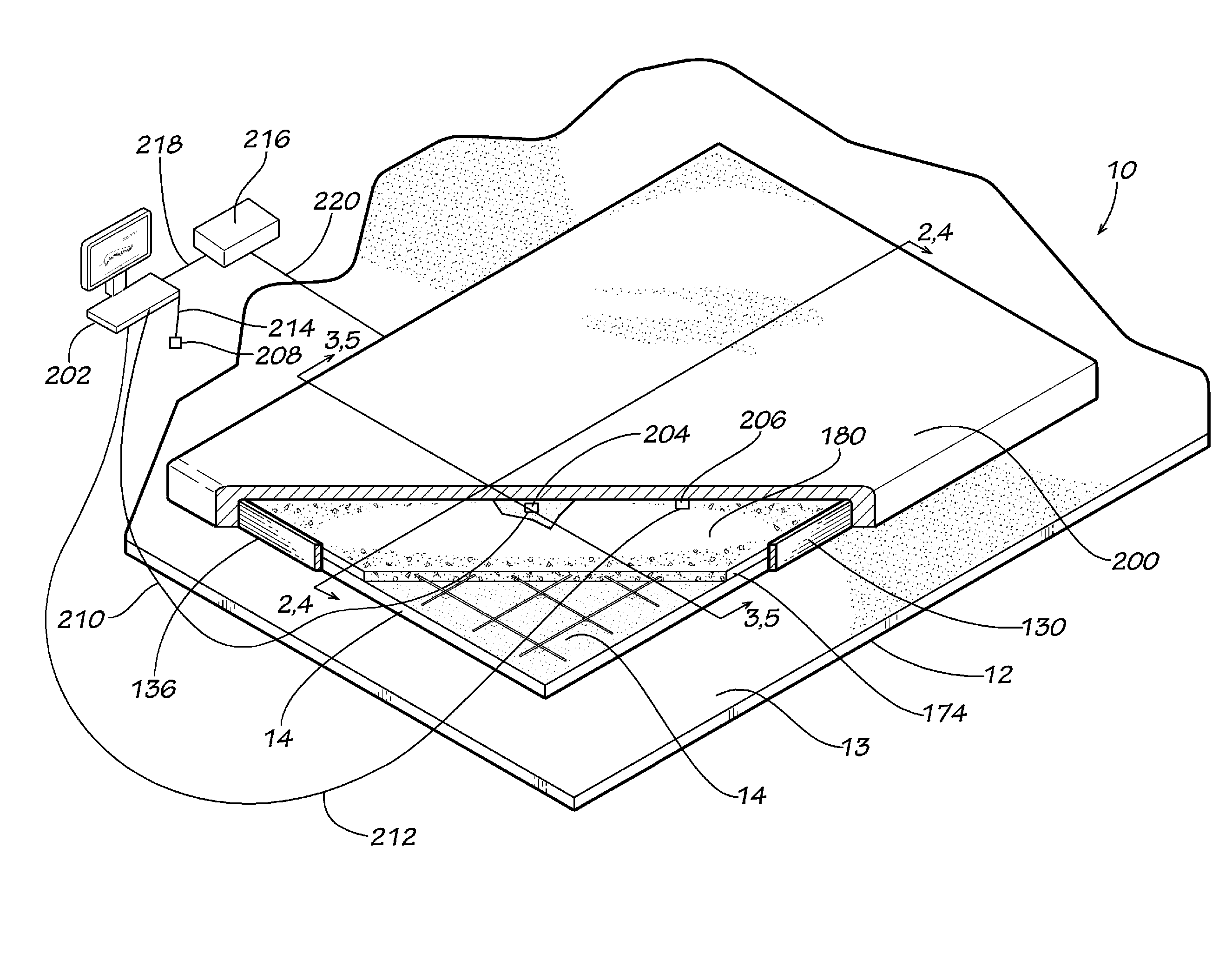
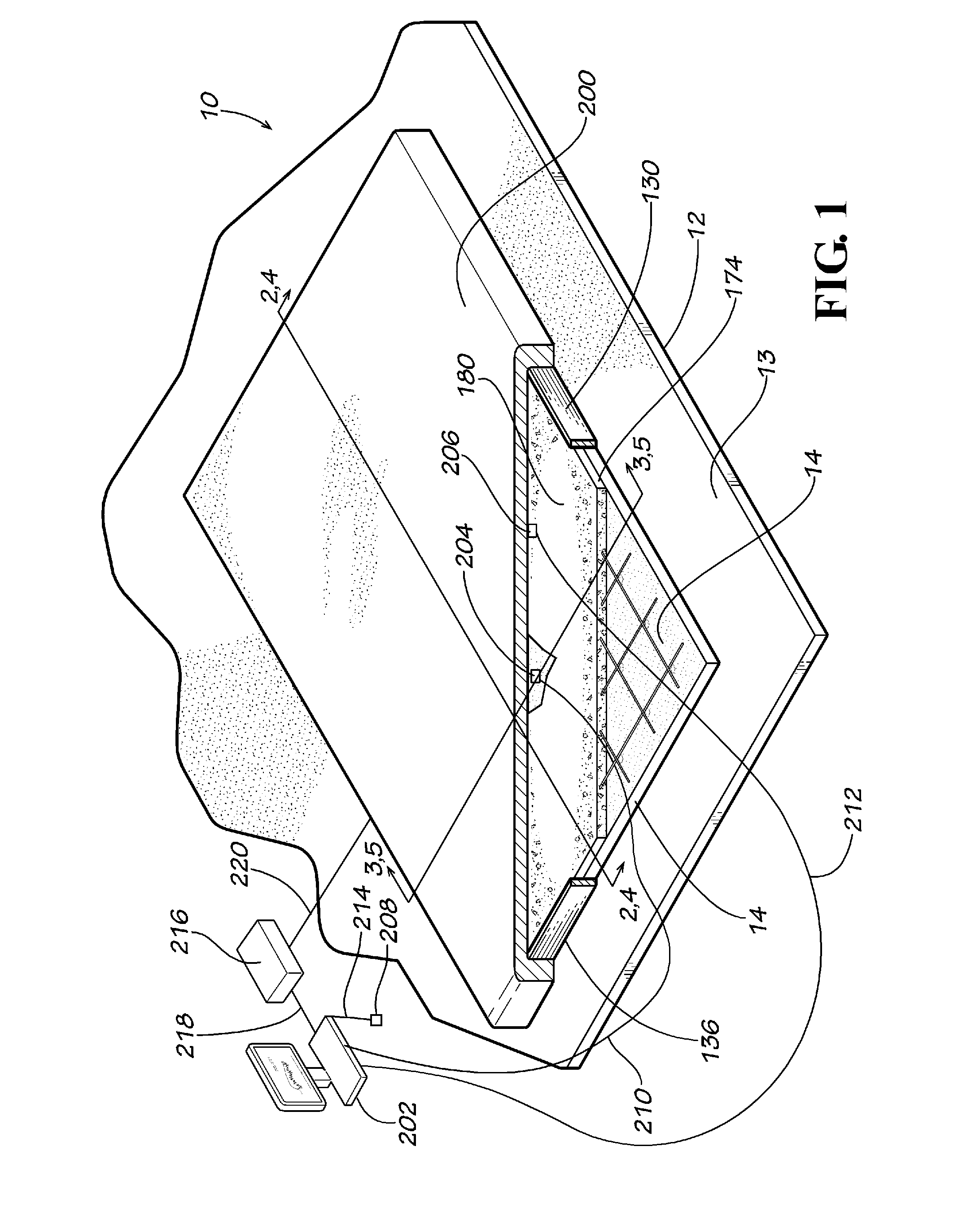
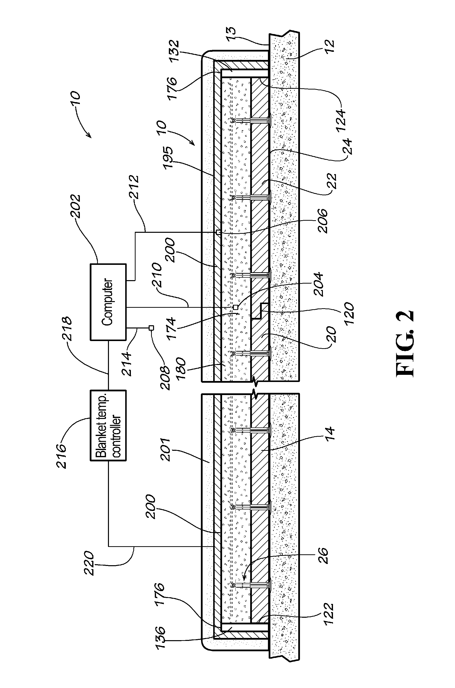
[0080]Referring now to the drawing in which like numbers indicate like elements throughout the several views, there is shown in FIG. 1 a disclosed embodiment of a precast insulated concrete form 10 in accordance with the present invention. The precast insulated concrete form 10 rests horizontally on a previously formed, and at least partially cured, concrete slab 12, which forms a floor of a proposed building (not shown). Alternately, the insulated concrete form 10 can be used on any solid, level, casting surface (not shown). The con...


PUM


Abstract

The invention comprises a method of forming a concrete structure or object. The method comprises detecting the temperature of a quantity of curing concrete and selectively adding heat to the curing concrete, so that the temperature of the curing concrete follows a predetermined temperature profile during at least a portion of the concrete curing process. Apparatus for performing the method is also disclosed.

Description

FIELD OF THE INVENTION[0001]The present invention generally relates to concrete curing. More particularly, this invention relates to a system for controlling the temperature of concrete in a concrete form or mold, particularly an insulated concrete form or mold. The present invention also relates to curing concrete over time in a concrete form or mold according to a predetermined temperature profile to achieve increased concrete strength. The present invention also relates to curing concrete to accelerated concrete maturity or equivalent age of concrete to achieve improved physical properties. The present invention also relates to a system for controlling the temperature differential in concrete, especially mass concrete.BACKGROUND OF THE INVENTION[0002]Concrete walls, and other concrete structures and objects, traditionally are made by building a form or a mold. The forms and molds are usually made from wood, plywood, metal and other structural members. Unhardened (plastic) concret...

Claims


Application Information

Patent Timeline
Patent Type & Authority Applications(United States)
IPC IPC(8): B28B11/24
CPCB28B11/24B28B7/42B28B17/0081E04G9/10E04G13/00E04G21/246C04B28/08C04B40/04C04B40/0096C04B40/0263C04B7/02C04B18/08Y02W30/91B29C39/00H05B1/0227
Inventor CIUPERCA, ROMEO ILARIAN
Owner CIUPERCA ROMEO ILARIAN
Why Eureka
Try Eureka