Motor control apparatus for hybrid vehicles

a technology of motor control and hybrid vehicles, applied in vehicle position/course/altitude control, process and machine control, instruments, etc., can solve the problems of reducing gain, affecting responsiveness, and instability of motor torque, so as to ensure responsiveness, reduce deviation, and stabilize the torque of the motor

Active Publication Date: 2014-03-27
DENSO CORP
View PDF2 Cites 10 Cited by
  • Summary
  • Abstract
  • Description
  • Claims
  • Application Information

AI Technical Summary

Benefits of technology

[0008]It is thus desired to provide a motor control apparatus for a hybrid vehicle, which is able to ensure responsiveness of motor rotation speed control (control of the rotation speed of a motor), while stabilizing the torque of the motor.
[0009]There is provided an apparatus for controlling a motor equipped in a hybrid vehicle equipped with, in addition to the motor having a rotation shaft, an engine, a power train, and wheels, motive power from the engine being transmitted to the wheels via the power train, the motor being connected to the power train such that motive power from the motor is transmitted to the power train, the apparatus comprising: first torque command value calculating means for calculating a basic torque command value of the motor so as to reduce a deviation between a target rotation speed of the motor and an actual rotation speed of the motor; torque correction value calculating means for calculating a torque correction value for the motor based on a variation of the target rotation speed which is obtained per unit time and a value of inertia of the power train rotated integrally with the rotation shaft of the motor; and second torque command value calculating means for calculating a torque command value finally supplied to the motor, by correcting the basic torque command value with use of the torque correction value.
[0010]With this configuration, the gain for calculating the basic torque command value is reduced to some extent so as to reduce the deviation between the target rotation speed and the actual rotation speed of the motor. Thus, the variation of the basic torque command value due to the rotation fluctuation of the engine is suppressed and thus the final torque command value is suppressed from being varied, thereby stabilizing the torque of the motor.
[0011]Further, the torque correction value is calculated on the basis of the variation of the target rotation speed and the inertia value. Using the torque correction value, the basic torque command value is corrected to thereby obtain the final torque command value. Thus, the final torque command value can be set by feed-forwardly correcting the basic torque command value. In this way, the responsiveness of the motor rotation speed control is suppressed from being impaired and thus the rotation speed deviation of the motor (deviation of the actual rotation speed with respect to the target rotation speed) can be reduced.

Problems solved by technology

In such a case, when the gain of the PI control is large, the torque command value for the motor may vary (oscillated) due to the fluctuation in the actual rotation speed of the motor, raising a problem of causing instability in the torque of the motor.
However, reducing the gain of the PI control may raise another problem of impairing the responsiveness of the motor rotation speed control, thereby increasing the rotation speed deviation (deviation of the actual rotation speed with respect to the target rotation speed) of the motor.

Method used


Image

  • Motor control apparatus for hybrid vehicles
  • Motor control apparatus for hybrid vehicles
  • Motor control apparatus for hybrid vehicles

Examples


first embodiment

[0020]Referring to FIGS. 2 to 5, a first embodiment of the present invention is described.

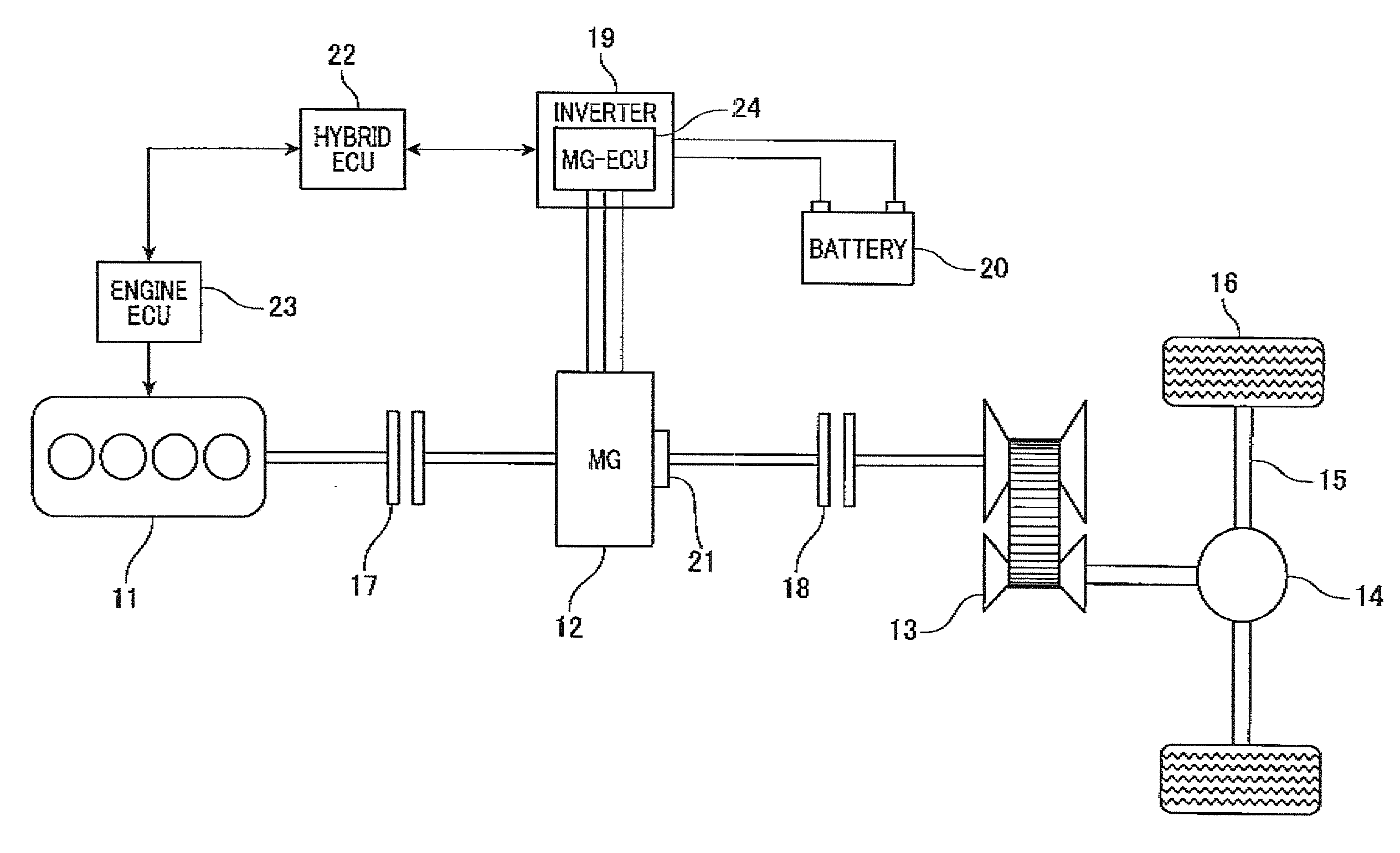
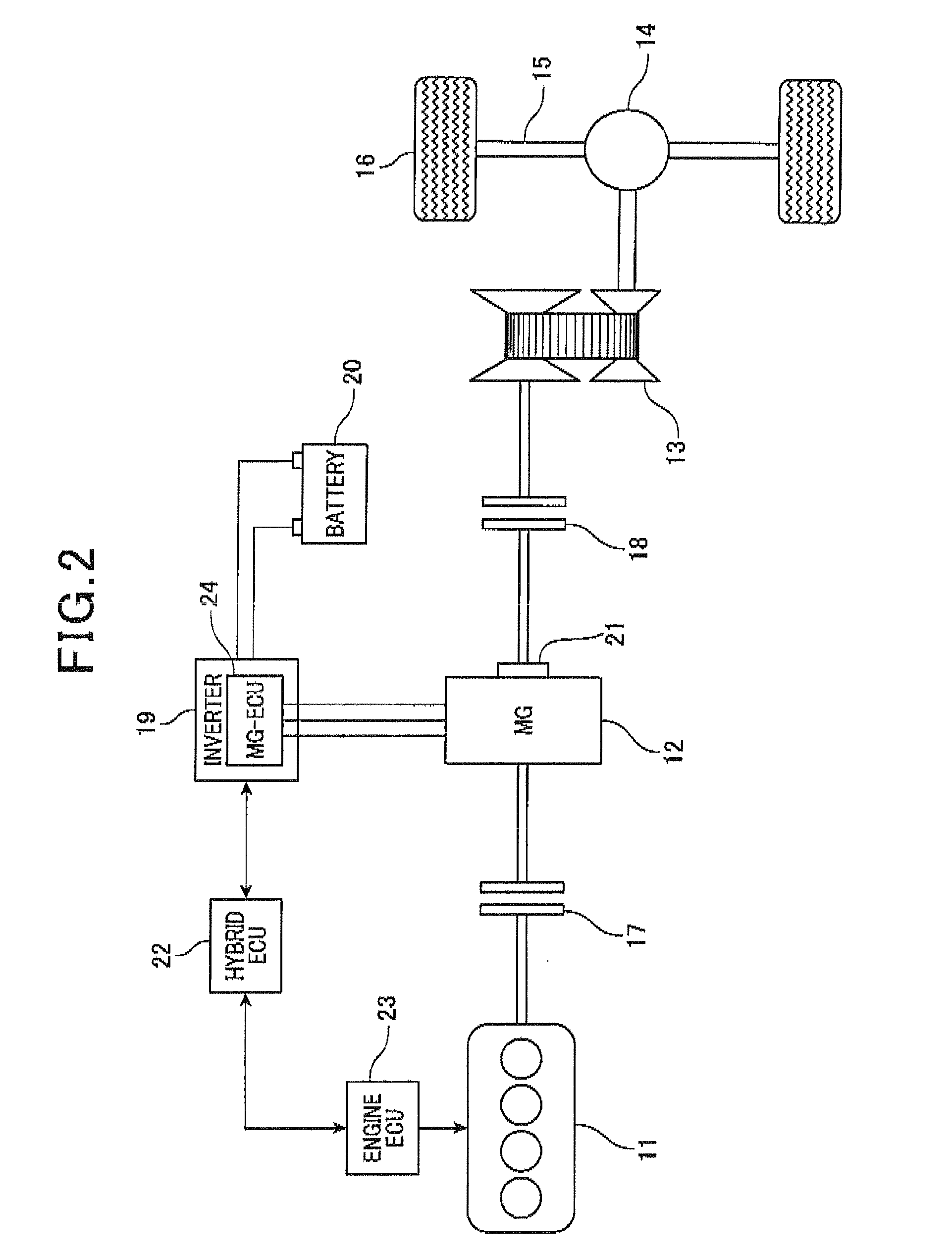
[0021]FIG. 2 is a schematic diagram illustrating a drive system of a hybrid vehicle, according to the first embodiment. As shown in FIG. 2, the drive system includes an engine 11 that is an internal combustion engine and a motor-generator (hereinafter is referred to as “MG”) 12 as motive power sources of the vehicle. The motive power of an output shaft (crank shaft) of the engine 11 is transmitted to a transmission 13 via the MG 12. Then, the motive power of an output shaft of the transmission 13 is transmitted to wheels 16 via a differential gear mechanism 14, an axle shaft 15 and the like. The transmission 13 may be a step transmission in which a gear range is changed stepwise among a plurality of gear ranges, or may be a CVT (continuously variable transmission) in which a gear range is changed in a stepless manner.

[0022]The engine 11 and the transmission 13, which configure a power train for...

second embodiment

[0052]Referring now to FIG. 6, hereinafter is described a second embodiment of the present invention. In the second embodiment, the components identical with or similar to those in the first embodiment are given the same reference numerals for the sake of omitting unnecessary explanation. The following description is given focusing on the differences from the first embodiment.

[0053]When the first clutch 17 is in a disconnected state, the rotation fluctuation of the MG 12 due to the rotation fluctuation of the engine 11 does not occur. Therefore, torque of the MG 12 can be stabilized by only tuning PI control, while responsiveness of the motor rotation speed control is ensured (i.e. no torque correction value is required).

[0054]In light of this, in the second embodiment, the MG-ECU 24 performs a motor rotation speed control routine shown in FIG. 6, which will be specifically described later. In this routine, the torque correction value Tj is calculated when the first clutch 17 is in ...


PUM


Abstract

An apparatus controls a motor equipped in a hybrid vehicle. In this apparatus, a basic torque command value of the motor is calculated so as to reduce a deviation between a target rotation speed and an actual rotation speed of the motor. A torque correction value for the motor is calculated based on a variation of the target rotation speed which is obtained per unit time and a value of inertia of a power train rotated integrally with the rotation shaft of the motor. Further, a torque command value finally supplied to the motor is calculated by correcting the basic torque command value with use of the torque correction value.

Description

CROSS-REFERENCE TO RELATED APPLICATION[0001]This application is based on and claims the benefit of priority from earlier Japanese Patent Application No. 2012-212493 filed Sep. 26, 2012, the description of which is incorporated herein by reference.BACKGROUND OF THE INVENTION[0002]1. Technical Field of the Invention[0003]The present invention relates to a motor control apparatus for a hybrid vehicle that has an engine and a motor as motive power sources of the vehicle.[0004]2. Related Art[0005]Recently, hybrid vehicles have come to capture attention. In light of the growing societal needs for good fuel efficiency and low emission of exhaust gas, hybrid vehicles have an engine and a motor installed as motive power sources of the vehicles. As disclosed in JP-A-2009-143360, for example, such a hybrid vehicle includes a system which is provided with a first element (e.g., the rotating part of a dog clutch) whose rotation is controlled by the motor and a second element (e.g., the stationar...

Claims


Application Information

Patent Timeline
Patent Type & Authority Applications(United States)
IPC IPC(8): B60W20/00B60W10/08B60W10/02B60W10/06B60L50/16
CPCB60W20/00B60W10/06Y10S903/93B60W10/02B60W10/08B60K6/48B60K6/543B60W30/20B60W2510/0208B60W2510/0266B60W2510/0695B60W2510/081B60W2510/088B60W2710/081B60W2710/083Y02T10/62Y02T10/72
Inventor KAWASAKI, SHINGO
Owner DENSO CORP
Why Eureka
Try Eureka