Method for temperature compensation in sensor, computation program for method for temperature compensation, computation processing device, and sensor

a technology of temperature compensation and sensor, applied in the direction of liquid/fluent solid measurement, machines/engines, instruments, etc., can solve the problem of disadvantageous difficulty in using a thinner diaphragm to increase pressure sensitivity, and achieve the effect of preventing gas leakage in the closed space and reliability of electric connection

Inactive Publication Date: 2014-03-27
JAPAN SCI & TECH CORP
View PDF4 Cites 4 Cited by
  • Summary
  • Abstract
  • Description
  • Claims
  • Application Information

AI Technical Summary

Benefits of technology

[0032](4) In the method for temperature compensation in the sensor in (3), preferably, the sensor includes a barrier metal layer containing at least platinum and formed between the second electrode portion and the insulator layer, the barrier metal layer having an inner circumferential surface forming a part of the closed space. Here, the “barrier metal” refers to a material such as metal which exerts the following advantageous effects: the material (1) allows a dense film to be formed and produces a barrier effect against reaction between a wiring material and a silicon substrate, (2) is bonded well to metal and an insulating film, (3) can be micromachined by dry etching, and (4) offers reduced resistance.
[0033]The configuration in (4) applies the result of optimization of the parameter ΔC′ to the capacitive sensor. Thus, the capacitive sensor configured to enjoy the barrier metal effect of the barrier metal layer can also detect a change in the capacitance between the diaphragm portion and both the first electrode portion and the conductive portion more accurately than in the conventional art.
[0034](5) In the method for temperature compensation in the sensor in (2), preferably, the conductive portion is a sealing ring portion formed on a surface of the diaphragm portion opposite to the surface of the diaphragm portion on which the temperature compensation ring is formed, and the sensor includes a ring-like second electrode portion formed between the sealing ring portion and the insulator layer to detect a change in the capacitance between the diaphragm portion and both the first electrode portion and the second electrode portion based on the deformation of the diaphragm portion.
[0035]The configuration in (5) applies the result of optimization of the parameter ΔC′ to the capacitive sensor. Thus, while configured to enjoy an effect enabling possible leakage of the gas in the closed space to be more reliably prevented by using the sealing ring to seal the portion between the diaphragm portion and the second electrode portion, the capacitive sensor can also detect a change in the capacitance between the diaphragm portion and both the first electrode portion and the second electrode portion more accurately than in the conventional art.
[0036](6) In the method for temperature compensation in the sensor in (5), preferably, the second electrode portion and the sealing ring portion of the sensor are bonded together by a gold-gold bonding.
[0037]The configuration in (6) applies the result of optimization of the parameter ΔC′ to the capacitive sensor. Thus, while configured to enjoy an effect enabling reliability of an electric connection between the second electrode portion and the sealing ring portion to be improved, the capacitive sensor can also detect a change in the capacitance between the diaphragm portion and both the first electrode portion and the second electrode portion more accurately than in the conventional art.

Problems solved by technology

Thus, for the pressure sensor used at about 1 atm, it is disadvantageously difficult to use a thinner diaphragm to increase pressure sensitivity.

Method used


Image

  • Method for temperature compensation in sensor, computation program for method for temperature compensation, computation processing device, and sensor
  • Method for temperature compensation in sensor, computation program for method for temperature compensation, computation processing device, and sensor
  • Method for temperature compensation in sensor, computation program for method for temperature compensation, computation processing device, and sensor

Examples


first embodiment

[0072]A method for temperature compensation in a sensor according to a first embodiment of the present invention will be described below with reference to FIG. 1 to FIG. 6.

[0073](Configuration of a Capacitive Sensor 100)

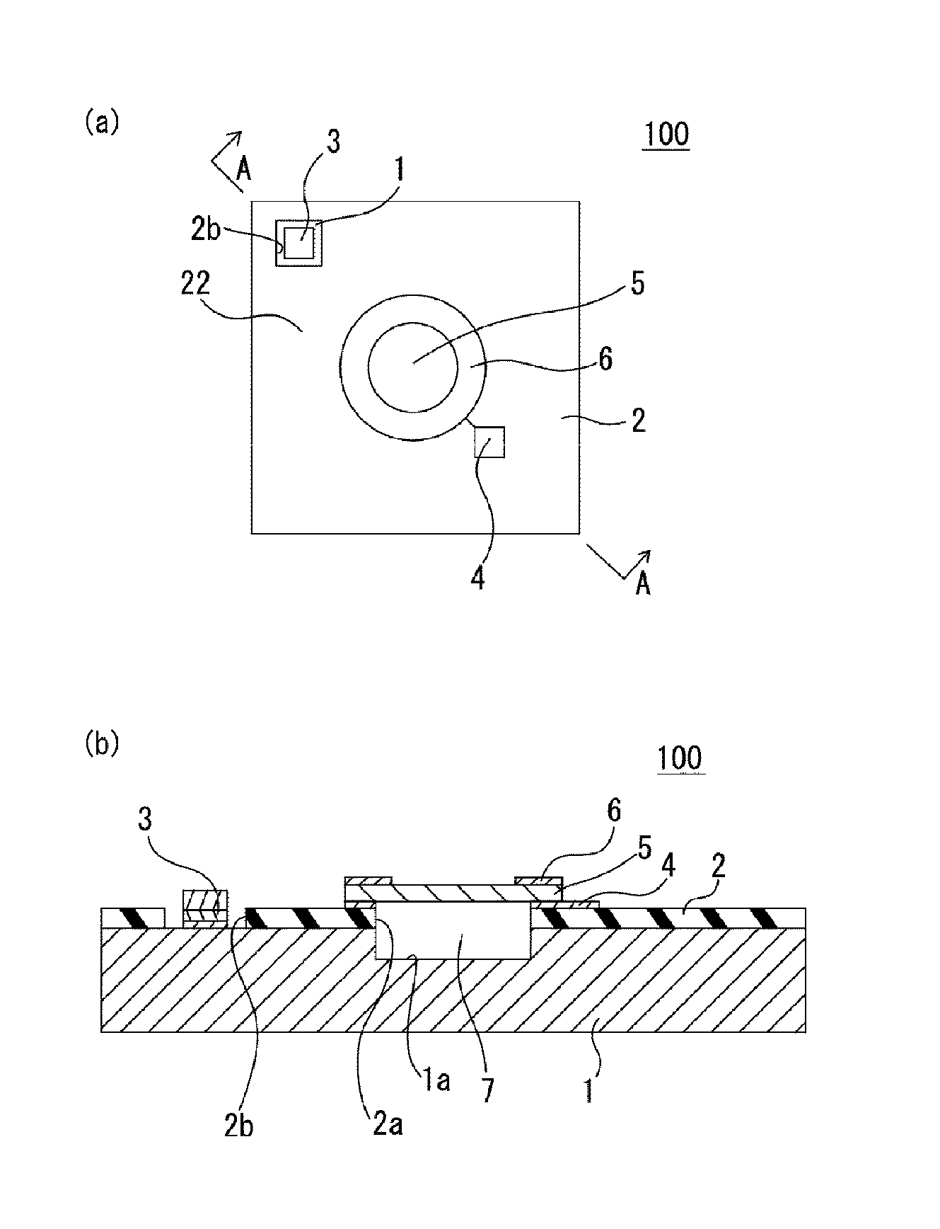
[0074]As shown in FIG. 1(a) and FIG. 1(b), a capacitive sensor (a sensor) 100 to which the results of computations in a method for temperature compensation in the capacitive sensor are applied includes a substrate 1, an insulator layer 2, a first electrode portion 3, a second electrode portion (conductive portion) 4, a diaphragm portion 5, a temperature compensation ring (temperature compensation member) 6, and a closed space 7.

[0075]The substrate 1 is formed of a semiconductor such as silicon and has a circular recess 1a in a substantially central portion of the substrate 1.

[0076]The insulator layer 2 is a layer formed of an insulator such as silicon dioxide and is formed on one surface of the substrate 1. The insulator layer 2 also has a circular penetration portio...

second embodiment

[0113]Now, a method for temperature compensation in a sensor according to a second embodiment of the present invention will be described with reference to FIG. 7 to FIG. 10. Portions 21 to 27 (some of the portions are not shown in the drawings) of a capacitive sensor 200 to which the results of computations in the method for temperature compensation according to the second embodiment are applied are similar to the portions 1 to 7, respectively, of the capacitive sensor 100 to which the results of computations in the method for temperature compensation according to the first embodiment are applied. Thus, description of the portions 21 to 27 may be omitted.

[0114](Configuration of the Capacitive Sensor 200)

[0115]As shown in FIG. 7, the capacitive sensor (the sensor) 200 includes a substrate 21, an insulator layer 22, a first electrode portion 23, a second electrode portion (conductive portion) 24, a diaphragm portion 25, a temperature compensation ring (temperature compensation member)...

third embodiment

[0122]Now, a method for temperature compensation in a sensor according to a third embodiment of the present invention will be described with reference to FIG. 11 to FIG. 14. Portions 31 to 37 (some of the portions are not shown in the drawings) of a capacitive sensor 300 to which the results of computations in the method for temperature compensation according to the third embodiment are applied are similar to the portions 1 to 7, respectively, of the capacitive sensor 100 to which the results of computations in the method for temperature compensation according to the first embodiment are applied. Thus, description of the portions 31 to 37 may be omitted.

[0123](Configuration of the Capacitive Sensor 300)

[0124]As shown in FIG. 11, the capacitive sensor (the sensor) 300 includes a substrate 31, an insulator layer 32, a first electrode portion 33, a second electrode portion 34, a diaphragm portion 35, a temperature compensation ring (temperature compensation member) 36, and a closed spa...


PUM

PropertyMeasurementUnit
pressure sensitivityaaaaaaaaaa
pressureaaaaaaaaaa
inner diameteraaaaaaaaaa

Abstract

Temperature compensation is performed using a computation program for temperature compensation, a computation processing, and a sensor. Deformation in a diaphragm caused by a pressure change due to the temperature of the gas in a cavity is cancelled out, and deformation of the diaphragm is minimized within the target temperature range, thereby allowing an optimum temperature compensation to be performed. The temperature compensation in a capacitance-type sensor executes calculation steps which include including a calculation step (S17) of acquiring the amount of change ΔC′ in capacitance. A parameter ΔC′ is obtained, through which it is possible to determine the degree of compensation for the deformation in the diaphragm section caused by a pressure change due to the temperature changes of the gas in the hermetically sealed space.

Description

TECHNICAL FIELD[0001]The present invention relates to a method for temperature compensation in a sensor, a computation program for the method for temperature compensation, a computation processing device carrying out a computation process of the computation program, and a sensor that is subjected to the temperature compensation.BACKGROUND ART[0002]A semiconductor pressure sensor conventionally includes a micro-cavity and a thin diaphragm that covers a surface of the micro-cavity, and serves as a pressure gauge by measuring a change in a resistance formed on a surface of the diaphragm resulting from deformation of the diaphragm caused by external pressure, or with another electrode provided on the opposite pole, measuring a change in the capacitance between the diaphragm and the counter electrode.[0003]In a pressure sensor configured as described above, in cases where the inside of the cavity is vacuumed and sealed, the deformation of the diaphragm is caused by a difference between o...

Claims


Application Information

Patent Timeline
Patent Type & Authority Applications(United States)
IPC IPC(8): G01L9/12
CPCG01L9/125B81B3/0081B81B2201/0264G01L9/0073G01L19/04
Inventor HAO, XIUCHUNJIANG, YONGGANGFUJITA, TAKAYUKIHIGUCHI, KOHEIMAENAKA, KAZUSUKETAKAO, HIDEKUNI
Owner JAPAN SCI & TECH CORP
Why Eureka
Try Eureka