Stabilized high-voltage power supply

a high-voltage power supply and stable technology, applied in the direction of three-or-more-wire dc circuits, transmission systems, electric variable regulation, etc., can solve the problems of emc problems, two requirements are difficult if not impossible to meet simultaneously, and the successful design of cathode power supplies is considered a challenge, etc., to achieve stable total output voltage, low voltage ripple, large

Active Publication Date: 2014-04-10
AMPEGON POWER ELECTRONICS AG
View PDF8 Cites 29 Cited by
  • Summary
  • Abstract
  • Description
  • Claims
  • Application Information

AI Technical Summary

Benefits of technology

[0016]It is therefore an object of the present invention to provide a high-voltage power supply that is capable of providing a stable total output voltage having low voltage ripple while being able to handle large, rapid current changes.

Problems solved by technology

This presents a considerable challenge to the successful design of a cathode power supply.
These two requirements are difficult if not impossible to satisfy simultaneously.
Furthermore, parasitic capacitances of the transformer may propagate the PWM frequency and its harmonics back into the mains grid, which may lead to EMC problems.
If, on the other hand, only coarse-step modulation is used without employing PWM, considerable ripple from the mains may result, and voltage regulation can only occur stepwise.
These power supplies cannot overcome the deficiencies noted above in connection with the more traditional kinds of PSM power supplies if both a rapid response to current changes and low voltage ripple are needed, since stabilization of the total output voltage still either requires PWM or, in the alternative, can be only carried out stepwise.

Method used


Image

  • Stabilized high-voltage power supply
  • Stabilized high-voltage power supply
  • Stabilized high-voltage power supply

Examples


Embodiment Construction

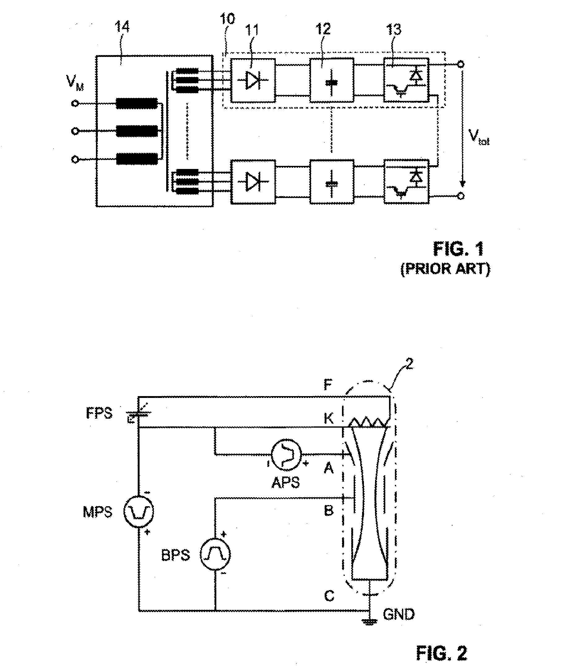
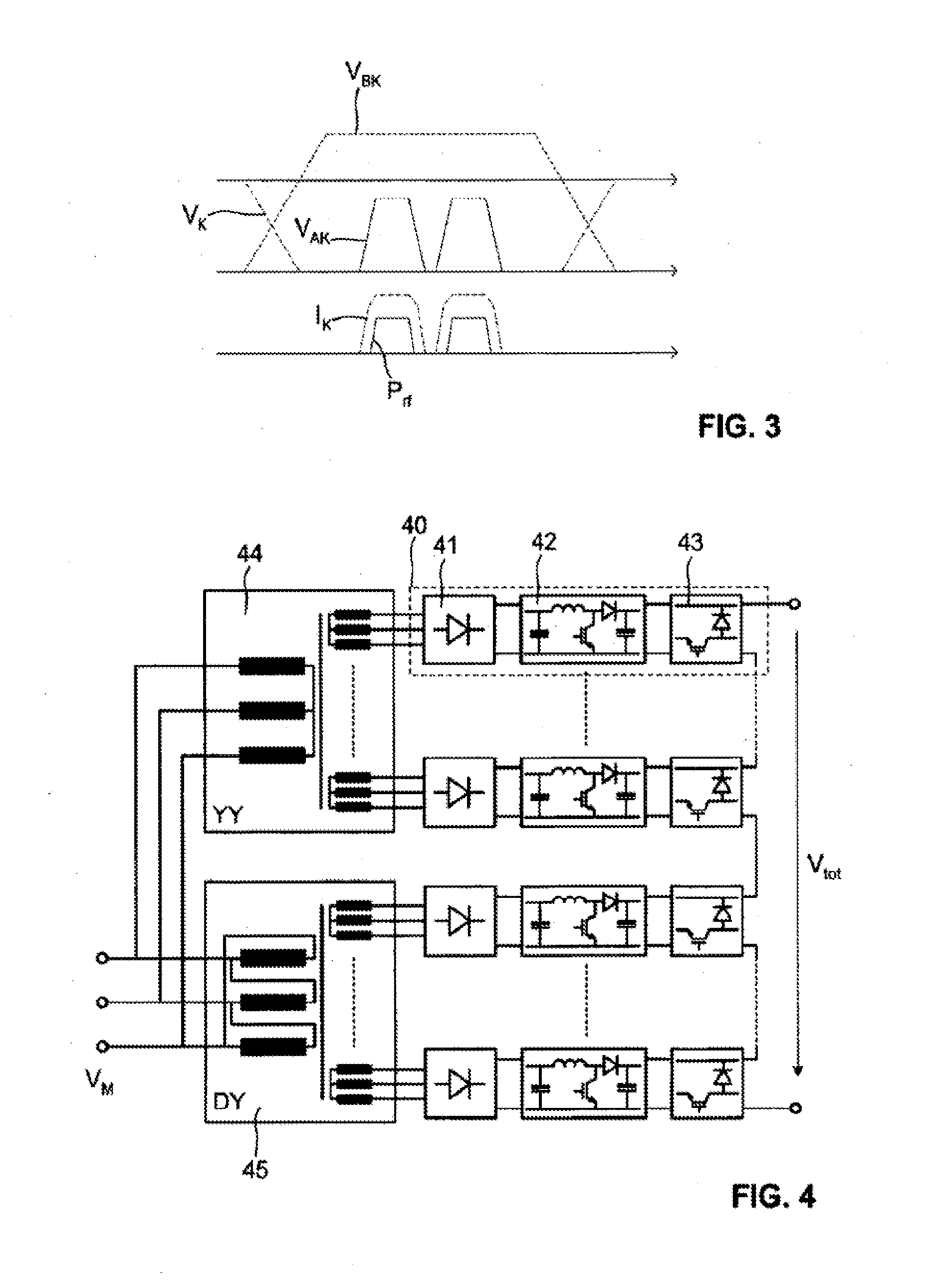
[0053]FIG. 3 illustrates, in a highly schematic fashion and not to scale, a typical sequence of the various voltages and currents involved in the operation of a gyrotron. At the beginning of the sequence, the cathode power supply MPS and the body power supply BPS are switched to their nominal output voltages to provide a predetermined beam voltage VBK. Both voltages are actively controlled to ensure stability of these voltages. The anode-cathode voltage VAK provided by the anode power supply APS is initially kept at a value which avoids any significant beam current between the cathode K and the collector C. Only when the gyrotron is to generate electromagnetic radiation, the anode-cathode voltage VAK is switched to a positive value, leading to a rapid rise of the beam current IK and to the emission of electromagnetic radiation with power Prf.

[0054]From this diagram it is apparent that the cathode power supply MPS must be capable of rapidly reacting to large variations in beam curren...


PUM


Abstract

A stabilized high-voltage power supply is disclosed, having a general setup similar to a pulse-step modulator. The power supply comprises a plurality of DC power modules (40) having their outputs connected in a series configuration. Each power module comprises a DC voltage source (41), a DC-DC converter (42), and an output switching circuit (43). The total output voltage of the power supply is regulated by regulating the DC link voltage at the output of each power module. This is achieved by an appropriate feedback control circuit driving the DC-DC converter of each power module. In this manlier, low output ripple and a rapid response to changes in output current can be achieved. The power supply may be used, e.g., as the cathode power supply of a gyrotron.

Description

TECHNICAL FIELD[0001]The present invention relates to a high-voltage power supply comprising a plurality of DC power modules connected in series, each module providing a DC link voltage that may be selectively switched. This general setup is often called a “pulse-step modulator” (PSM).PRIOR ART[0002]Pulse-step modulators are widely used as voltage supplies for high-power vacuum tubes in various applications, in particular, as modulation amplifiers in AM transmitters or radar systems. An early example of a pulse-step modulator is disclosed, e.g., in EP 0 066 904.[0003]A typical prior-art pulse-step modulator is illustrated in FIG. 1. The modulator comprises a plurality of identical DC power modules 10 connected to the secondaries of a multi-secondary transformer 14. Each module comprises a rectifier circuit 11 and a smoothing capacitance 12 for providing a DC link voltage, and a switching circuit 13 for selectively providing the DC link voltage to the output of the module. A free-whe...

Claims


Application Information

Patent Timeline
Patent Type & Authority Applications(United States)
IPC IPC(8): H01J23/00G05F1/10H02J1/00
CPCH01J23/34H01J25/025H02J1/08H02M2001/0003H02M2001/007H02M2001/0077Y10T307/685H02M1/0003H02M1/007H02M1/0077
Inventor BADER, MICHAEL
Owner AMPEGON POWER ELECTRONICS AG
Why Eureka
Try Eureka