Capacity control valve

Active Publication Date: 2014-04-10
EAGLE INDS
View PDF7 Cites 13 Cited by
  • Summary
  • Abstract
  • Description
  • Claims
  • Application Information

AI Technical Summary

Benefits of technology

[0025]The present invention has the following excellent effects.
[0026](1) When the first valve part opens, the discharged-fluid-receiving part receives the pressure of the discharged fluid. Therefore, it is possible to obtain a capacity control valve in which the actuation response of the valve body during the opening action is moderated, an excessive increase in the sensitivity to a rise in pressure in the crank chamber caused by a rapid increase in the amount of coolant flowing into the crank chamber is prevented, and the action of the valve body is stable. Therefore, in air-conditioning control using an automotive air-conditioning device in which there is used a swash plate variable capacity compressor fitted with the capacity control valve of the present invention, it is possible to prevent any occurrence of temperature fluctuation in the vehicle compartment, adverse effect on air conditioning control, torque fluctuation in the compressor, adverse effect on the engine, and other problems.
[0027]Also, since the engaging surface of the third valve part that engages with the seat surface of the adapter has a tapered shape, the third valve part and the adapter can be engaged/disengaged with respect to each other in a straightforward and reliable manner.
[0028](2) The surface of the discharged-fluid-receiving part that receives the discharged fluid being provide

Problems solved by technology

If the sensitivity to the rise in pressure in the crank chamber increases excessively, there may be instances in which the discharge capacity decreases excessively, the action of the valve body 81 becomes unstable, resulting in unstable phenomena such as “hunting.” This tendency is more likely to occur if the valve body 81 has a high actuation response.
With

Method used


Image

  • Capacity control valve
  • Capacity control valve
  • Capacity control valve

Examples


Embodiment Construction

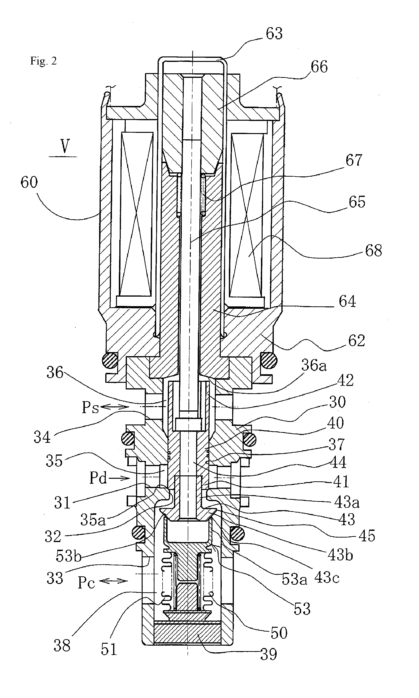
[0037]An embodiment of the capacity control valve according to the present invention will now be described in detail with reference to the accompanying drawings. However, this is not provided by way of limitation to the interpretation of the present invention; a variety of modifications, amendments, and improvements based on the knowledge of a person skilled in the art are possible without departing from the scope of the present invention.

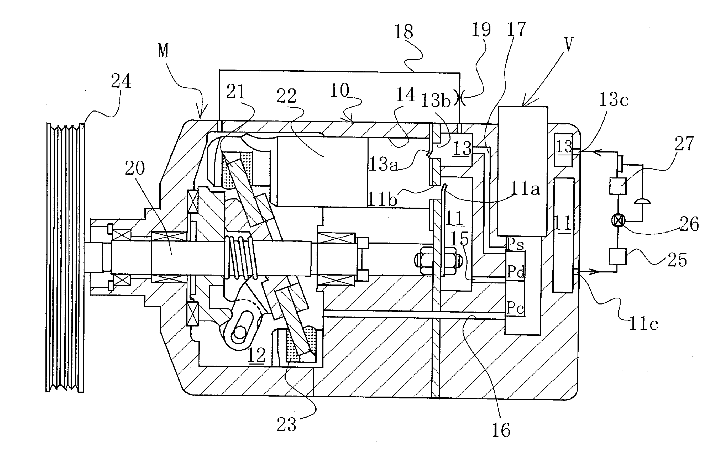
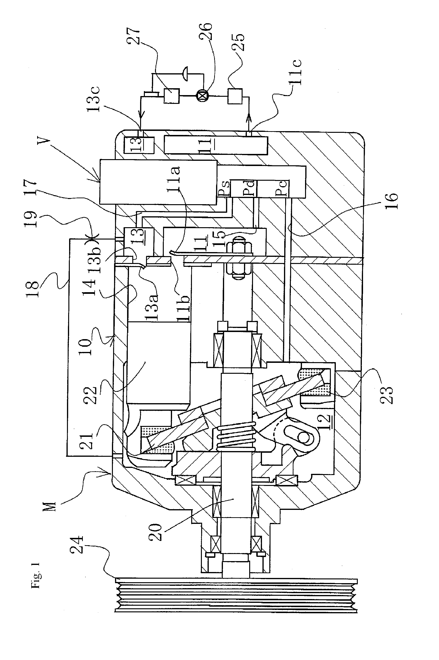
[0038]A swash plate variable capacity compressor M comprises, as shown in FIG. 1: a discharge chamber 11; a control chamber (also referred to as a crank chamber) 12; an intake chamber 13; a plurality of cylinders 14; a port 11b interconnecting the cylinders 14 and the discharge chamber 11, the port 11b being opened / closed by a discharge valve 11a; a port 13b interconnecting the cylinders 14 and the intake chamber 13, the port 13b being opened / closed by an intake valve 13a; a discharge port 11c and an intake port 13c connected to an external cooling...


PUM


Abstract

In a capacity control valve, a discharged-fluid-receiving part having a diameter that is larger than the diameter of a valve hole interconnecting a first valve chamber and a third valve chamber is provided to the outer periphery section of a third valve part. It is thereby possible to obtain a capacity control valve in which, when the first valve part opens, the discharged-fluid-receiving part receives the pressure of the discharged fluid, the actuation response of the valve body during an opening action is moderated, an excessive increase in the sensitivity to a rise in pressure in the crank chamber caused by a rapid increase in the amount of coolant flowing into the crank chamber is prevented, and the action of the valve body is stable.

Description

TECHNICAL FIELD[0001]The present invention relates to a capacity control valve for variably controlling the capacity or the pressure of a working fluid, and particularly to a capacity control valve for controlling, according to pressure load, the discharge amount of, e.g., a variable capacity compressor used in an air conditioning system for an automobile and the like.BACKGROUND ART[0002]Swash plate variable capacity compressors used in air conditioning systems for automobiles or other applications comprise: a rotary shaft, which is rotatably driven by the rotating force of the engine; a swash plate, connected to the rotary shaft so that the tilt angle is variable; a piston for compression, connected to the swash plate; and other components. The tilt angle of the swash plate is varied, whereby the stroke of the piston is varied and the amount of the coolant gas discharged is controlled.[0003]The tilt angle of the swash plate can be continuously changed by appropriately controlling t...

Claims


Application Information

Patent Timeline
IPC IPC(8): G05D7/01F04B27/18
CPCG05D7/0106F04B27/1804F04B2027/1827F04B2027/1845F04B27/08F04B27/14F16K11/076F16K31/363
Inventor FUKUDOME, KOHEIHIGASHIDOUZONO, HIDEKIFUTAKUCHI, MASAYUKI
Owner EAGLE INDS
Why Eureka
Try Eureka