Water-cooled condenser

Inactive Publication Date: 2014-04-17
CALSONIC KANSEI CORP
View PDF19 Cites 24 Cited by
  • Summary
  • Abstract
  • Description
  • Claims
  • Application Information

AI Technical Summary

Benefits of technology

The patent text discusses the design of a front section of a vehicle for collision safety. However, the current designs have drawbacks such as reduced heat radiation performance due to reduced cooling airflow volume, limited design options due to reduced space in the front section, and potential refrigerant leakage in a small collision. The technical effects aim to address these drawbacks and provide a more optimized design for the front section of a vehicle.

Problems solved by technology

Since front surfaces of the condenser and the sub-radiator are covered by the bumper reinforcement, cooling airflow volume reduces and thereby heat radiation performance reduces.
In addition, a size of the sub-radiator becomes large due to the built-in water-cooled condenser in the side tank of the sub-radiator, so that designing of layout is restricted in a case of a vehicle whose front section has a relatively narrow space.
In addition, a pipe(s) is protruded forward from the water-cooled condenser, so that arrangement of the bumper reinforcement in a front section of a vehicle becomes difficult and refrigerant leakage from the refrigerant pipe(s) protruded forward is apprehended in a slight collision to a front section of a vehicle.
However, installation of a water-cooled condenser is not considered in the configuration.

Method used


Image

  • Water-cooled condenser
  • Water-cooled condenser
  • Water-cooled condenser

Examples


first embodiment

[0022](First Embodiment)

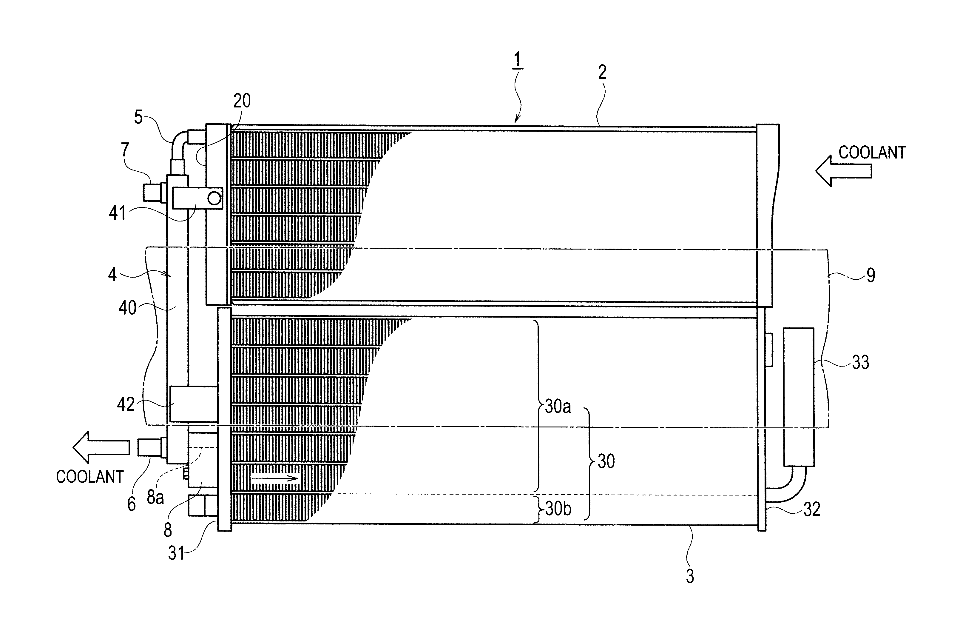
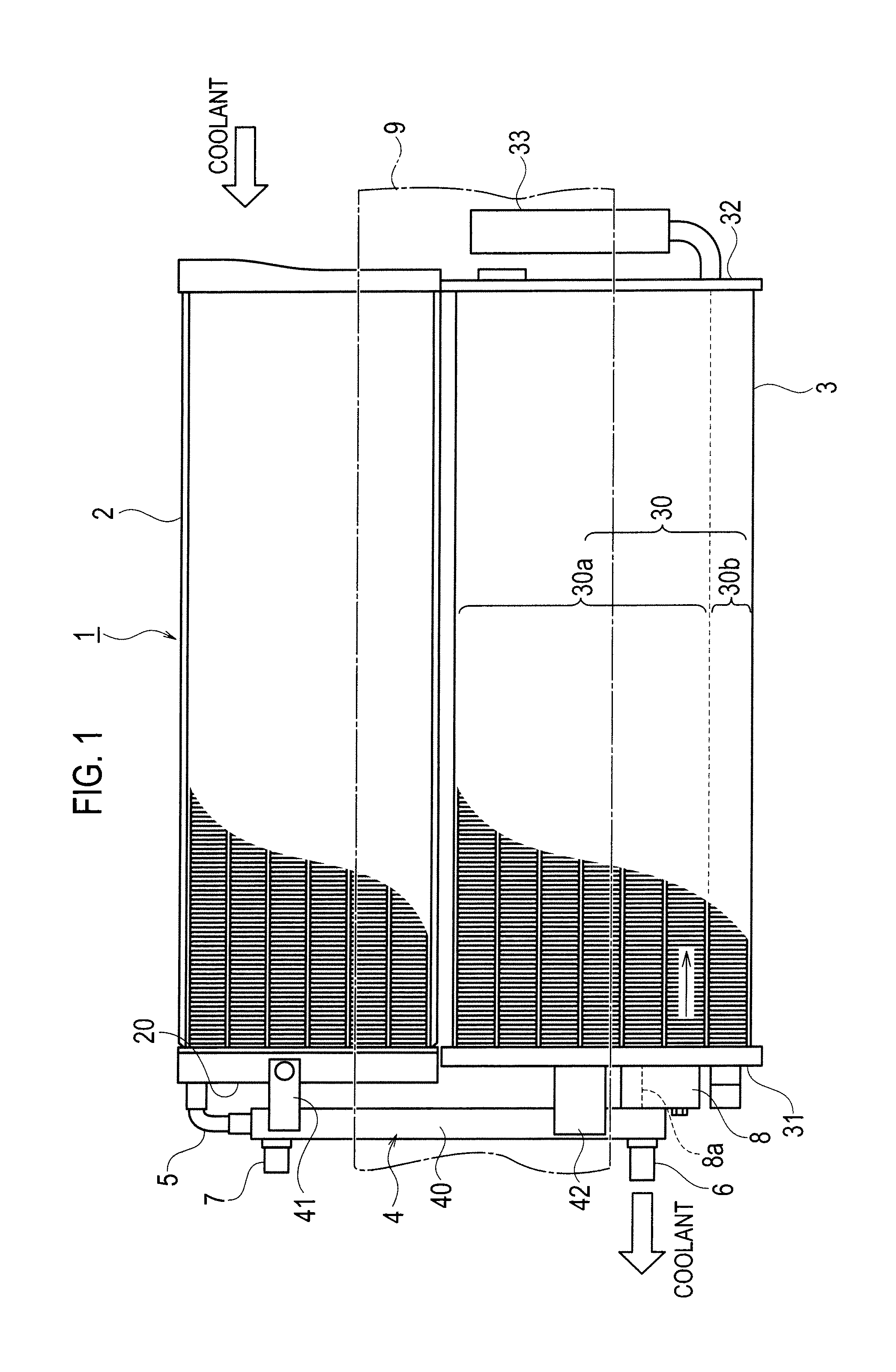
[0023]As shown in FIG. 1, the combined heat exchanger 1 includes a sub-radiator 2, an in-compartment air-cooled condenser 3, and a water-cooled condenser 4. The sub-radiator 2 exchanges heat between coolant for cooling a heat-generating object (e.g. an inverter when a vehicle is an EV or an HEV) and outside air (to reduce temperature of the coolant). The air-cooled condenser 3 is disposed under the sub-radiator 2, and exchanges heat between refrigerant for air-conditioning and outside air (to reduce temperature of the refrigerant). The water-cooled condenser 4 is disposed beside (on a left side in FIG. 1) the sub-radiator 2 and the air-cooled condenser 3. A bumper reinforcement 9 for collision safety is disposed in front of the sub-radiator 2, the air-cooled condenser 3, and the water-cooled condenser 4.

[0024]The air-cooled condenser 3 includes a core 30, and a pair of a first tank 31 and a second tank 32. In the core 30, tubes and heat-radiation fins are ver...

second embodiment

[0039](Second Embodiment)

[0040]As shown in FIG. 5, in a water-cooled condenser 4A according to the present embodiment, the intermediate connecting member 8 (refrigerant outlet port 8a) is connected with the first tank 31 of the air-cooled condenser 3 slightly above (closely above) (an upper edge of) the bumper reinforcement 9. The air-cooled condenser 3 is disposed above the sub-radiator 2, and the water-cooled condenser 4A is disposed beside (on a left side in FIG. 5) the sub-radiator 2 and the air-cooled condenser 3. Note that, in the present embodiment, components identical or equivalent to those in the first embodiment are labeled by the identical numbers.

[0041]The coolant that has flown out from the sub-radiator 2 flows into the water-cooled condenser 4 through a flexible coolant flow-in pipe 5A disposed at a lower end of the water-cooled condenser 4A. The coolant flows upward in an inner flow passage of the water-cooled condenser 4A, and then flows out from an upper portion of...


PUM


Abstract

A water-cooled condenser that exchanges heat between refrigerant of an air conditioner for a vehicle and coolant, and then send the refrigerant out to a air-cooled condenser through a refrigerant outlet port. The refrigerant outlet port is connected with the air-cooled condenser at a position that doesn't overlap a bumper reinforcement arranged in front of the air-cooled condenser at a front section of the vehicle when viewed along an airflow direction toward the air-cooled condenser. In the water-cooled condenser, the refrigerant that flows into the air-cooled condenser through the refrigerant outlet port flows much at a position that doesn't overlap the bumper reinforcement, so that superior heat radiation performance can be brought by a sufficient cooling airflow volume. Therefore, total heat radiation performance achieved by the air-cooled condenser and the water-cooled condenser can be improved.

Description

TECHNICAL FIELD[0001]The present invention relates to a water-cooled condenser, especially to a water-cooled condenser suitable for exchanging heat of refrigerant of an air-conditioner for a vehicle.BACKGROUND ART[0002]A Patent Document 1 and a Patent Document 2 listed below disclose a water-cooled condenser installed within a side tank of a sub-radiator. In addition, a Patent Document 3 listed below discloses an air-cooled condenser and a radiator arranged lower than a bumper reinforcement.PRIOR ART DOCUMENTPatent Documents[0003]Patent Document 1: Japanese Patent Application Laid-Open No. 2010-121604[0004]Patent Document 2: Japanese Patent Application Laid-Open No. 2010-127508[0005]Patent Document 3: Japanese Patent Application Laid-Open No. 2005-22474SUMMARY OF INVENTION[0006]In the configurations disclosed in the Patent Document 1 and the Patent Document 2, a bumper reinforcement is disposed at a front section of a vehicle for collision safety. Since front surfaces of the condens...

Claims


Application Information

Patent Timeline
IPC IPC(8): F28F9/26
CPCF28F9/26B60K11/04B60H1/3227B60K2001/003F28D1/0443F28D1/0461B60K11/02B60Y2306/01F28D2021/0084B60H1/00342
Inventor MATSUDAIRA, NORIMITSUMORI, EIICHI
Owner CALSONIC KANSEI CORP
Why Eureka
Try Eureka