

Polishing head and polishing apparatus
- Summary
- Abstract
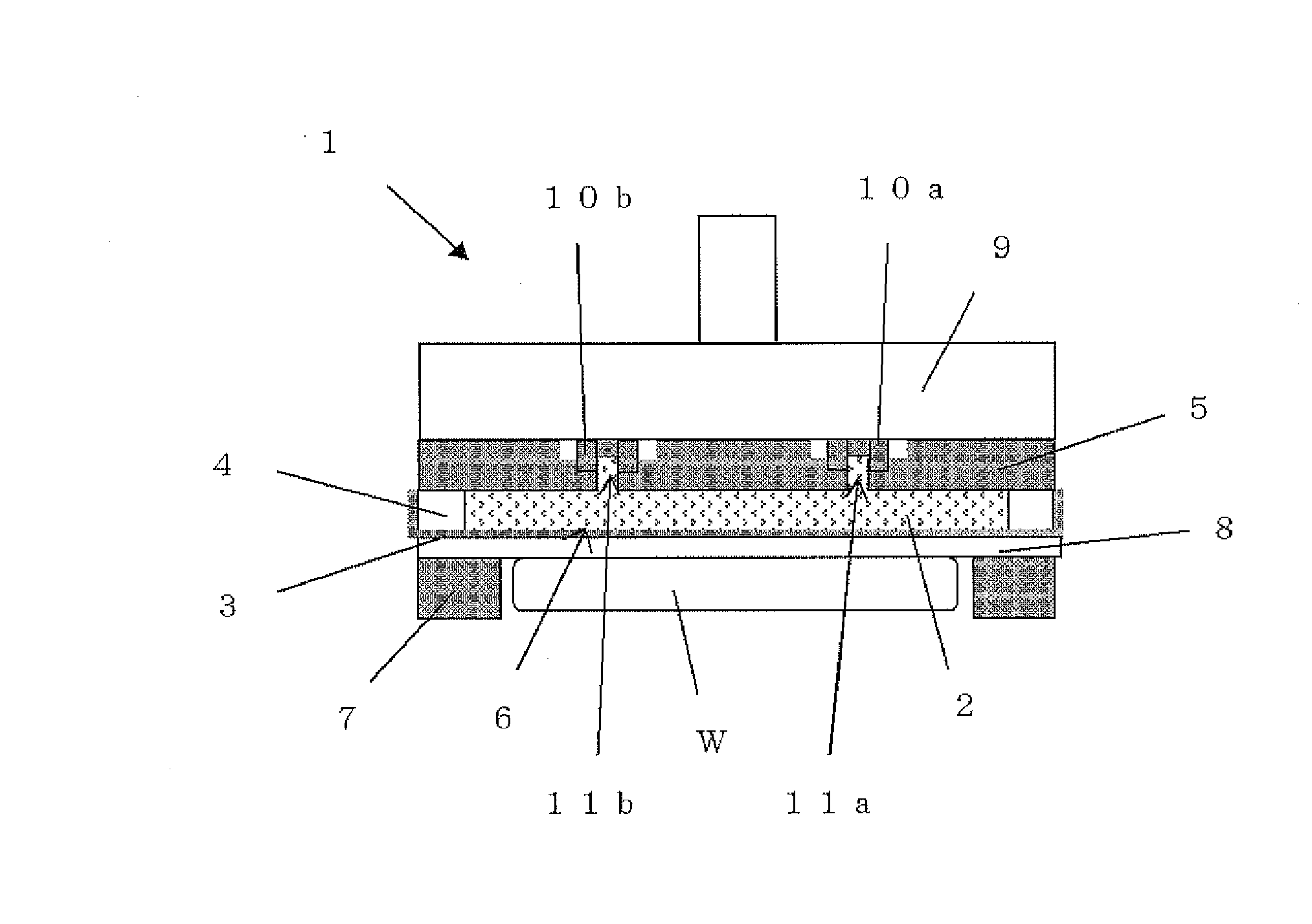
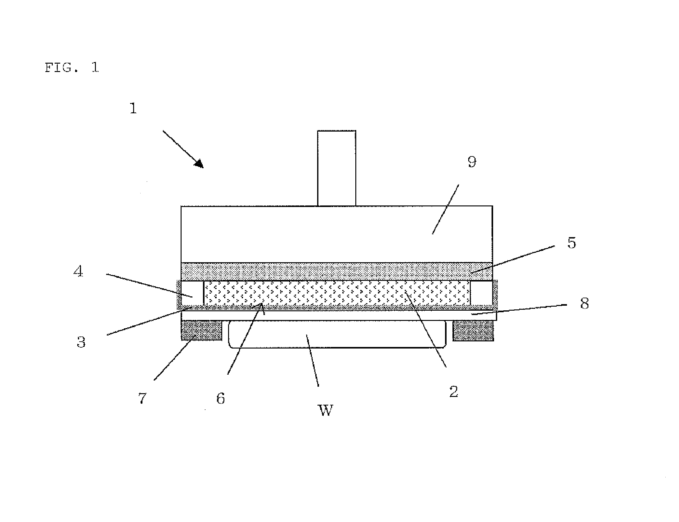
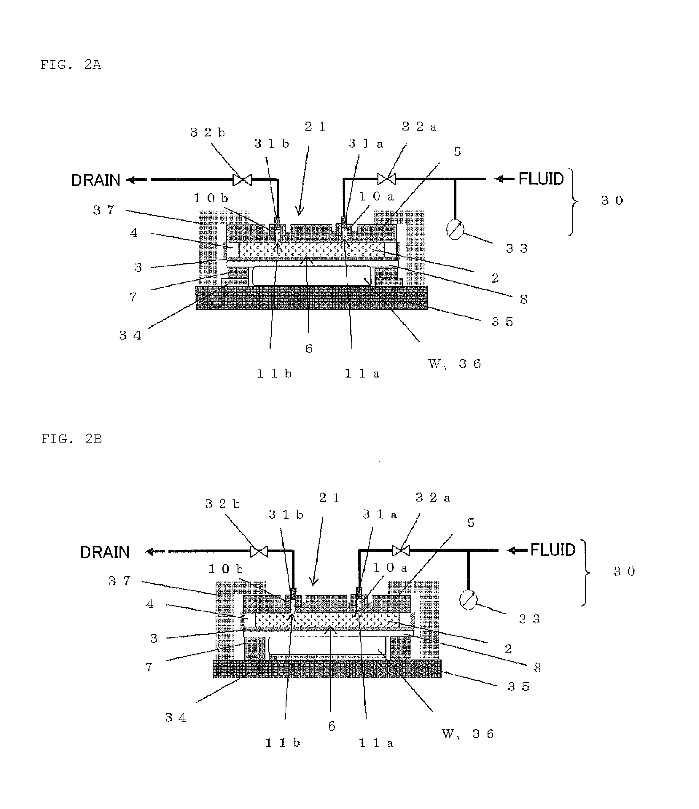
- Description
- Claims
- Application Information
AI Technical Summary
Benefits of technology
Problems solved by technology
Method used
Image

Examples
examples
[0093]Although the present invention will now be more specifically explained based on examples and comparative examples hereinafter, the present invention is not restricted thereto.
examples 1 to 3
[0094]A workpiece was polished with a polishing apparatus of the present invention including the polishing head as illustrated in FIG. 3, and variation in polishing stock removal in a plane of the polished workpiece was evaluated. A silicon single crystal wafer having a diameter of 300 mm and a thickness of 775 μm was used as the workpiece W. The polishing stock removal was calculated by measuring both the thicknesses of the wafer before and after polishing with a flatness measuring instrument in a region excluding a width 2 mm of the outermost peripheral portion as a flatness-guaranteed region and by obtaining differences between the thicknesses before and after polishing in a cross section of the wafer along a diametric direction. A flatness measuring instrument (WaferSight) manufactured by KLA-Tencor was used for measuring the flatness.
[0095]The following polishing heads were prepared: A rigid ring composed of SUS with an outer diameter of 360 mm and an inner diameter of 320 mm w...
examples 4 to 7
[0104]A silicon single crystal wafer was polished under the same conditions as those of Example 1 except that silicon rubber was attached under conditions of a tensile force of 5 N (Example 4), 20 N (Example 5), 35 N (Example 6), and 48 N (Example 7), and the variation in polishing stock removal in a plane of the polished wafer was evaluated as with Example 1.
[0105]FIG. 7A shows the polishing stock removal distribution of the wafer polished in each of Examples 4 to V. FIG. 7B shows the polishing stock removal distribution in the range from 120 mm to 148 mm away from the wafer center as a polishing stock removal distribution of an outer peripheral portion of the wafer. As shown in FIGS. 7A and 7B, it can be understood that the wafer was polished uniformly up to the outer peripheral portion in each of Examples 4 to 7.
[0106]Additionally, as an index representing the polishing stock removal distribution at the outer peripheral portion of the wafer, a difference between a maximum value a...
PUM
 Abstract
Description
Claims
Application Information