Vacuum system comprising vacuum insulated glass units

a vacuum system and vacuum technology, applied in water supply installation, machines/engines, transportation and packaging, etc., can solve the problem of pressure in the vacuum space of a vig unit to quickly exceed service pressure, and achieve the effect of speeding up the process of outgassing, increasing outgassing rate, and speeding up the removal of absorbed and adhering gas molecules

Inactive Publication Date: 2014-05-01
JONES ROBERT S
View PDF8 Cites 10 Cited by
  • Summary
  • Abstract
  • Description
  • Claims
  • Application Information

AI Technical Summary

Benefits of technology

[0041]The process known as a “high temperature bakeout,” which is described below, is one way to speed up the process of outgassing and to attain low pressures within practical time frames. Unfortunately, as will be discussed below, this is not an option for a vacuum system comprising VIG units with polymer edge seals or spacers.
[0042]Raising the temperature of a vacuum chamber increases outgassing rates and speeds up the removal of absorbed and adhering gas molecules. This occurs because the added energy overcomes binding energies, increases diffusion rates, imparts energy to liberated molecules, and increases molecular conductance. When the chamber cools and returns to ambient temperatures, outgassing rates may be very much lower than when the process began. If the temperature increase during this outgassing process is high, the procedure is called a high temperature bakeout.

Problems solved by technology

Without removal, these outgassing products would cause the pressure in the vacuum space of a VIG unit to quickly exceed service pressures.

Method used


Image

  • Vacuum system comprising vacuum insulated glass units
  • Vacuum system comprising vacuum insulated glass units
  • Vacuum system comprising vacuum insulated glass units

Examples


Embodiment Construction

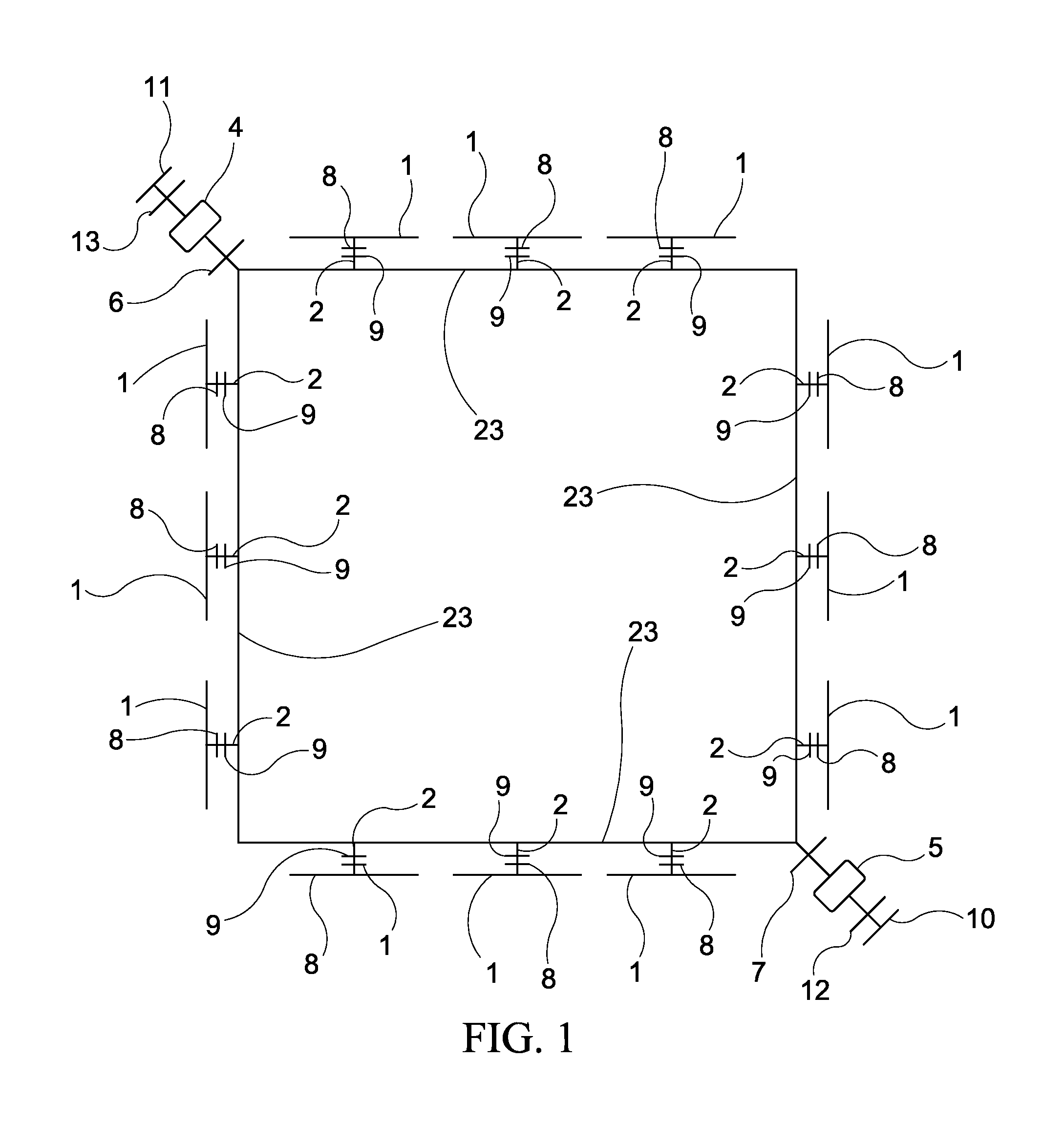
[0081]FIG. 1 shows a plan view schematic of a vacuum system comprising VIG units, vacuum valves, vacuum pumps, and a system of tubes and tubing stubs according to one embodiment of this invention. This might represent the layout on any given floor of a building, such as a skyscraper. The vacuum spaces of VIG units 1 are connected by piping stubs 2 to piping system 3. Piping system 3 is connected to a vacuum pump 4 or multiple pumps such as 4 and 5. There may be one or more vacuum valves such as vacuum gate valves 6 and 7 that can be closed to isolate the vacuum system from the atmosphere. Closing valves 6 and 7 will maintain low pressures in the vacuum spaces of VIG units 1 for some period of time, allowing pumps 4 and 5 to be turned off for service or removed for replacement. Vacuum valves 6 and 7 may be closed as a safety measure if there is a likelihood of a power failure. There may be one or more vacuum valves such as 8 and 9 between the vacuum spaces of VIG units 1 and a tubing...


PUM

PropertyMeasurementUnit
distanceaaaaaaaaaa
distanceaaaaaaaaaa
distanceaaaaaaaaaa

Abstract

Vacuum systems comprising vacuum insulating glass (VIG) units are provided. The vacuum spaces within the VIG units are connected to one another and to one or more vacuum pumps that are configured to operate during the service lives of the VIG units.

Description

CROSS REFERENCE TO RELATED APPLICATIONS[0001]The present application claims the benefit of priority of the following U.S. provisional applications: Ser. No. 61 / 718,406, filed on Oct. 25, 2012, and entitled “Vacuum Insulating Window with Multiple Stage Edge Seals;” Ser. No. 61 / 725,110, filed on Nov. 12, 2012, and entitled “Vacuum Insulating Window with Integral Vacuum Pump;” Ser. No. 61 / 732,577, filed on Dec. 3, 2012, and entitled “Vacuum Insulating Window Baked-Out after Installation and Method for Same;” Ser. No. 61 / 751,891, filed on Jan. 13, 2013, and entitled “Flapper Valve for Vacuum Insulating Window;” Ser. No. 61 / 760,854, filed on Feb. 5, 2013, and entitled “Hollow Cylindrical Spacer for Vacuum Insulating Window;” Ser. No. 61 / 767,379, filed on Feb. 21, 2013, and entitled “Cross Shaped Spacer for Vacuum Insulating Window;” Ser. No. 61 / 775,637, filed on Mar. 10, 2013, and entitled “Cross Shaped Polymer Spacer and Large Vacuum Gap for Vacuum Insulating Window;” Ser. No. 61 / 802,52...

Claims


Application Information

Patent Timeline
Patent Type & Authority Applications(United States)
IPC IPC(8): F17D5/00
CPCY02B80/24F17D5/00E06B3/677E06B3/6612E06B3/66304F17D1/00Y10T137/86083Y10T137/0318Y10T29/49826Y02B80/22E06B3/67326
Inventor JONES, ROBERT S.
Owner JONES ROBERT S
Why Eureka
Try Eureka