Hybrid integrated component

a hybrid, integrated technology, applied in the field of components, can solve problems such as complex circuit functions, and achieve the effects of reducing the influence of interfering effects, bending and vibration, and high sensitivity of the mems function

Active Publication Date: 2014-05-01
ROBERT BOSCH GMBH
View PDF7 Cites 13 Cited by
  • Summary
  • Abstract
  • Description
  • Claims
  • Application Information

AI Technical Summary

Benefits of technology

[0017]As already indicated, components, whose micromechanical function is based on a capacitive detection principle or excitation principle, represent a preferred application for the component concept according to the present invention. It has proven to be particularly advantageous in this context that the electrical functionality of the cap allows the implementation of differential capacitor systems having three electrode layers. For this purpose, the deflectable structural element is equipped with at least one electrode, which forms the middle electrode of such a differential capacitor system. The stationary “out of plane” electrodes are implemented, on the one hand, on the carrier and, on the other hand, on the cap. Using this type of capacitor system, a comparatively high sensitivity of the MEMS function may be achieved, since the area of the detection means is enlarged on a predefined available space. In addition, an improved offset stability may be achieved by more spatially separated detection means in the case of micromechanical acceleration sensors. In the case of micromechanical yaw rate sensors, in particular out-of-plane detecting sensors, the influence of interfering effects, such as bending and vibration, may be reduced by situating electrodes above and below the movable structure.

Problems solved by technology

However, it is also possible to provide individual sections of the cap with more complex circuit functions.

Method used


Image

  • Hybrid integrated component
  • Hybrid integrated component
  • Hybrid integrated component

Examples


Embodiment Construction

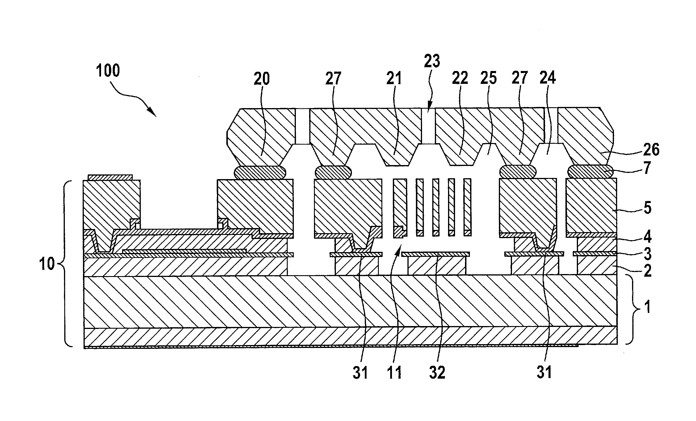
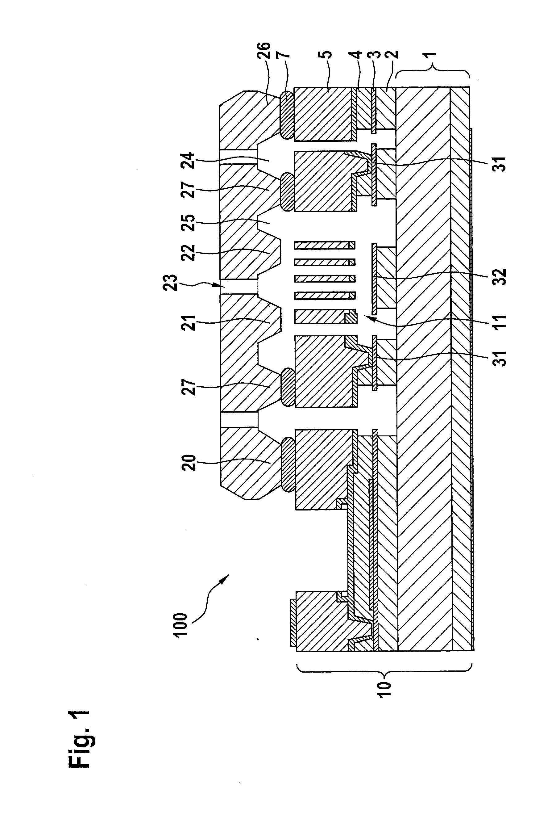
[0020]Sensor component 100 shown in FIG. 1 essentially includes a MEMS element 10 and a cap 20.

[0021]The functionality of MEMS element 10 is implemented in a layered structure on a semiconductor substrate 1. This may be a silicon substrate, for example. The layered structure includes a printed conductor layer 3 and a functional layer 5. Printed conductor layer 3 is implemented here in the form of a doped polysilicon layer, which was deposited above a first insulation layer 2 made of, for example, silicon oxide or silicon nitride on semiconductor substrate 1. The printed conductor layer may also be implemented, however, in the form of a metal layer, made of, for example, aluminum, copper, gold, or platinum. By structuring polysilicon layer 3, individual areas of printed conductor layer 3 were spatially separated from one another, in order to produce printed conductors, a terminal area 31 for the micromechanical sensor structure, and also a stationary electrode 32. A further insulatio...


PUM


Abstract

A component has at least one MEMS element and at least one cap made of a semiconductor material. The cap, in addition to its mechanical function as a terminus of a cavity and protection of the micromechanical structure, is provided with an electrical functionality. The micromechanical structure of the MEMS element of the component is situated in a cavity between a carrier and the cap, and includes at least one structural element which is deflectable out of the component plane within the cavity. The cap includes at least one section extending over the entire thickness of the cap, which is electrically insulated from the adjoining semiconductor material in such a way that it may be electrically contacted independently from the remaining sections of the cap.

Description

BACKGROUND OF THE INVENTION[0001]1. Field of the Invention[0002]The present invention relates to a component having at least one MEMS (micro-electromechanical system) element and having at least one cap made of a semiconductor material, the micromechanical structure of the MEMS element being situated in a cavity between a carrier and the cap and including at least one structural element, which is deflectable out of the element plane within the cavity.[0003]2. Description of the Related Art[0004]Components having MEMS elements have been manufactured in mass production for some years for greatly varying applications, for example, in the field of automotive technology and consumer electronics. The MEMS element may be a sensor element having detection means for detecting the deflection of the micromechanical structural element or also an actuator element having drive means for activating the deflectable structural element. The cap protects the micromechanical structure of the MEMS eleme...

Claims


Application Information

Patent Timeline
Patent Type & Authority Applications(United States)
IPC IPC(8): B81B7/00
CPCB81B7/0032B81C1/00246B81C1/0023B81C2203/075B81C2203/0771H01L2224/48463
Inventor CLASSEN, JOHANNESFRANKE, AXELFREY, JENSWEBER, HERIBERTFISCHER, FRANKWELLNER, PATRICKHATTASS, MIRKOMEISEL, DANIEL CHRISTOPH
Owner ROBERT BOSCH GMBH
Why Eureka
Try Eureka