System and method for finding correspondence between cameras in a three-dimensional vision system

a three-dimensional vision system and camera technology, applied in image analysis, image enhancement, instruments, etc., can solve the problems of more computation and processing overhead, limit the accuracy of stereo vision systems, and reduce the accuracy of overall pose determination process, so as to improve the speed and accuracy of the overall pose determination process.

Active Publication Date: 2014-05-01
COGNEX CORP
View PDF3 Cites 52 Cited by
  • Summary
  • Abstract
  • Description
  • Claims
  • Application Information

AI Technical Summary

Benefits of technology

[0012]This invention overcomes disadvantages of the prior art by providing a system and method for determining correspondence between camera assemblies in a 3D vision system implementation having a plurality of cameras arranged at different orientations with respect to a scene involving microscopic and near microscopic objects under manufacture moved by a manipulator, so as to acquire contemporaneous images of a runtime object and determine the pose of the object for the purpose of guiding manipulator motion. At least one of the camera assemblies includes a non-perspective lens. The searched 2D object features of the acquired non-perspective image, corresponding to trained object features in the non-perspective camera assembly can be combined with the searched 2D object features in images of other camera assemblies (perspective or non-perspective), based on their trained object features to generate a set of 3D features (3D locations of model features) and thereby determine a 3D pose of the object. In this manner the speed and accuracy of the overall pose determination process is improved as the non-perspective image is less sensitive to object tilt and other physical / optical variations.
[0013]In an embodiment, a plurality of non-perspective lenses and associated cameras are employed to acquire a plurality of respective non-perspective images. The intrinsics and extrinsics of each non-perspective camera allow the generation of a transform between images that enables the 3D pose to be efficiently determined based upon the searched locations of 2D features on planar surfaces of the object. The transform is illustratively an affine transform.

Problems solved by technology

The limitations of stereo vision systems are in part a result of small baselines among cameras, which requires more textured features in the scene, and reasonable estimation of the distance range of the object from the cameras.
Thus, the accuracy achieved may be limited to pixel level (as opposed to a finer sub-pixel level accuracy), and more computation and processing overhead is required to determine dense 3D profiles on objects.
However, there are significant challenges to obtaining accurate results with training models.
More particularly, the vision system application's searching speed and accuracy is affected due to the feature contrast level changes and shape changes (due to homographic projections) between cameras.
In any such arrangement there are challenges to registering an object in three-dimensions from trained images using this approach.
For example, when non-coplanar object features are imaged using a perspective camera with a conventional perspective (also termed “projective” in the art) lens (one in which the received light rays cross), different features of the acquired image undergo different transformations, and thus, a single affine transformation can no longer be relied upon to provide the registered pattern.
This effectively fools the 2D vision system into assuming an acquired image has a different shape than the trained counterpart, and more generally complicates the registration process.
While this approach is effective, it and other approaches are not optimal for systems using, for example, a differing type of lens arrangement, and would still benefit from increased accuracy of correspondences and decreased processor overhead.
More particularly, in certain robotic and / or pick-and-place applications at the microscopic and near microscopic range (e.g. generally involving objects or parts in motion that are between approximately 1-20 millimeters in size), it is often challenging to provide adequate guidance to the manipulator that receives, holds and delivers the object under manufacture (part).
This limits the speed of the overall manipulation operation.
However, such accurate fixturing can limit the versatility of the system, and concomitantly increase setup time and costs.

Method used


Image

  • System and method for finding correspondence between cameras in a three-dimensional vision system
  • System and method for finding correspondence between cameras in a three-dimensional vision system
  • System and method for finding correspondence between cameras in a three-dimensional vision system

Examples


Embodiment Construction

[0028]I. System Overview

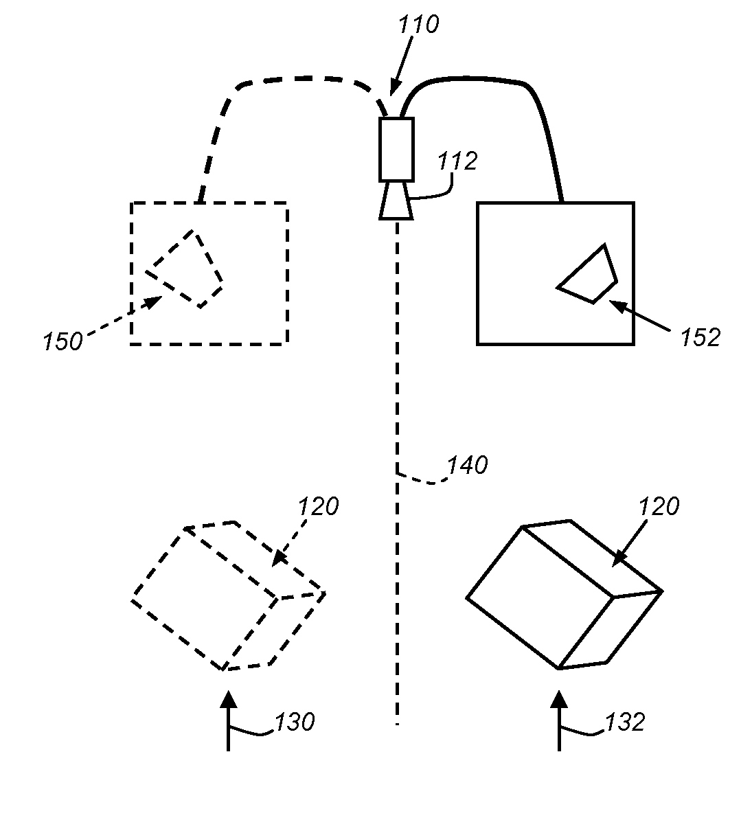
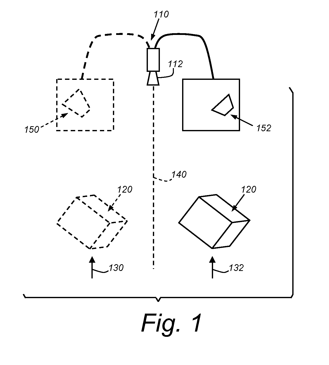
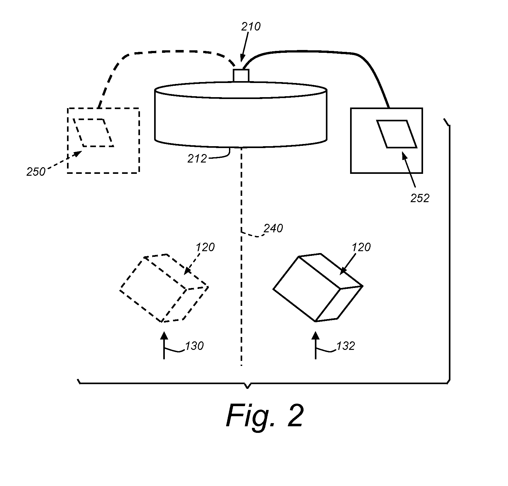
[0029]With reference to FIG. 2, a camera 210 is shown with an attached telecentric lens 212 of conventional design. The lens, 212 can have any parameters appropriate to the field of view of the object 120, which similar to that of FIG. 1, moves between two positions 130 and 132 with respect to the camera's field of view (centered about axis 240). Telecentricity (as opposed to perspective projection) has the advantage that the object's appearance remains essentially unchanged as it moves through the field of view. As shown, the resulting images 250 and 252 have a similar shape and appearance due to the elimination of perspective effects. This is achieved because the rays passing through a telecentric lens are parallel, as opposed to crossing, as is the case with a conventional perspective optical arrangement.

[0030]It should be noted that the illustrative telecentric lenses shown herein are shown as symbolic representations and not generally drawn to scale. Mor...


PUM


Abstract

This invention provides a system and method for determining correspondence between camera assemblies in a 3D vision system implementation having a plurality of cameras arranged at different orientations with respect to a scene involving microscopic and near microscopic objects under manufacture moved by a manipulator, so as to acquire contemporaneous images of a runtime object and determine the pose of the object for the purpose of guiding manipulator motion. At least one of the camera assemblies includes a non-perspective lens. The searched 2D object features of the acquired non-perspective image, corresponding to trained object features in the non-perspective camera assembly can be combined with the searched 2D object features in images of other camera assemblies, based on their trained object features to generate a set of 3D features and thereby determine a 3D pose of the object.

Description

RELATED APPLICATIONS[0001]This application is a continuation-in-part of co-pending U.S. patent application Ser. No. 12 / 962,918, filed Dec. 8, 2010, entitled SYSTEM AND METHOD FOR FINDING CORRESPONDENCE BETWEEN CAMERAS IN A THREE-DIMENSIONAL VISION SYSTEM, the entire disclosure of which is herein incorporated by reference.FIELD OF THE INVENTION[0002]The use of advanced machine vision systems and their underlying software is increasingly employed in a variety of manufacturing and quality control processes. Machine vision enables quicker, more accurate and repeatable results to be obtained in the production of both mass-produced and custom products. Typical machine vision systems include one or more cameras (typically having solid-state charge couple device (CCD) or CMOS-based imaging elements) directed at an area of interest, a frame grabber / image processing elements that capture and transmit CCD images, a computer or onboard processing device, and a user interface for running the mac...

Claims


Application Information

Patent Timeline
Patent Type & Authority Applications(United States)
IPC IPC(8): G06T7/00H04N13/02G06V10/147
CPCG06T7/0004H04N13/0203G06T2207/30164G06T2207/30208G06T2207/10012G06T2207/10056G06T7/80G06T7/75H04N13/204G06V10/147
Inventor LIU, LIFENGWALLACK, AARON S.MARRION, JR., CYRIL C.MICHAEL, DAVID J.
Owner COGNEX CORP
Why Eureka
Try Eureka