
Bellows driven air floatation abrading workholder

Inactive Publication Date: 2014-05-01
DUESCHER WAYNE O
View PDF36 Cites 13 Cited by
  • Summary
  • Abstract
  • Description
  • Claims
  • Application Information

AI Technical Summary

Benefits of technology

The patent describes a new technology for abrasive lapping or polishing of wafers that allows for very high speeds and uniform abrasion across the wafer surface. The technology includes flexible abrasive disks with precise thickness variations and a platen vacuum disk attachment system for quick changes in abrasive particles and material. The use of resilient wafer pads helps minimize surface damage from abrasion. The same chemicals used in conventional CMP polishing can be used with this system, and they are washed away from the abrefabricated surfaces to prevent unwanted abrasion. The high-speed system achieves higher material removal rates and increases production efficiency and cost savings. It also addresses the issue of vibration or oscillation of unstable workholders at high speeds to prevent uneven surface wear.

Problems solved by technology

The applied coolant water results in abrading debris being continually flushed from the abraded surface of the workpieces.

Method used


Image

  • Bellows driven air floatation abrading workholder
  • Bellows driven air floatation abrading workholder
  • Bellows driven air floatation abrading workholder

Examples


Embodiment Construction

[0042]FIG. 13 is a cross section view of a conventional prior art pneumatic bladder type of wafer carrier. A rotatable wafer carrier head 341 having a wafer carrier hub 342 is attached to the rotatable head (not shown) of a polishing machine tool (not shown) where the carrier hub 342 is loosely attached with flexible joint device 352 and a rigid slide-pin 350 to a rigid carrier plate 338. The cylindrical rigid slide-pin 350 can move along a cylindrical hole 349 in the carrier hub 342 which allows the rigid carrier plate 338 to move axially along the hole 349 where the movement of the carrier plate 338 is relative to the carrier hub 342. The rigid slide-pin 350 is attached to a flexible diaphragm 360 that is attached to carrier plate 338 which allows the carrier plate 338 to be spherically rotated about a rotation point 358 relative to the rotatable carrier hub 342 that is remains aligned with its rotational axis 346.

[0043]A sealed flexible elastomeric diaphragm device 364 has a numb...


PUM


Abstract

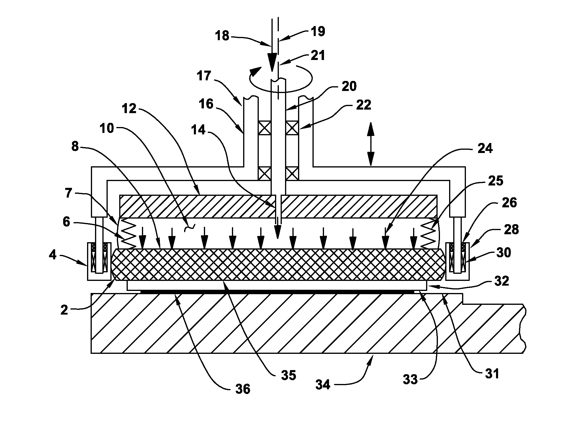
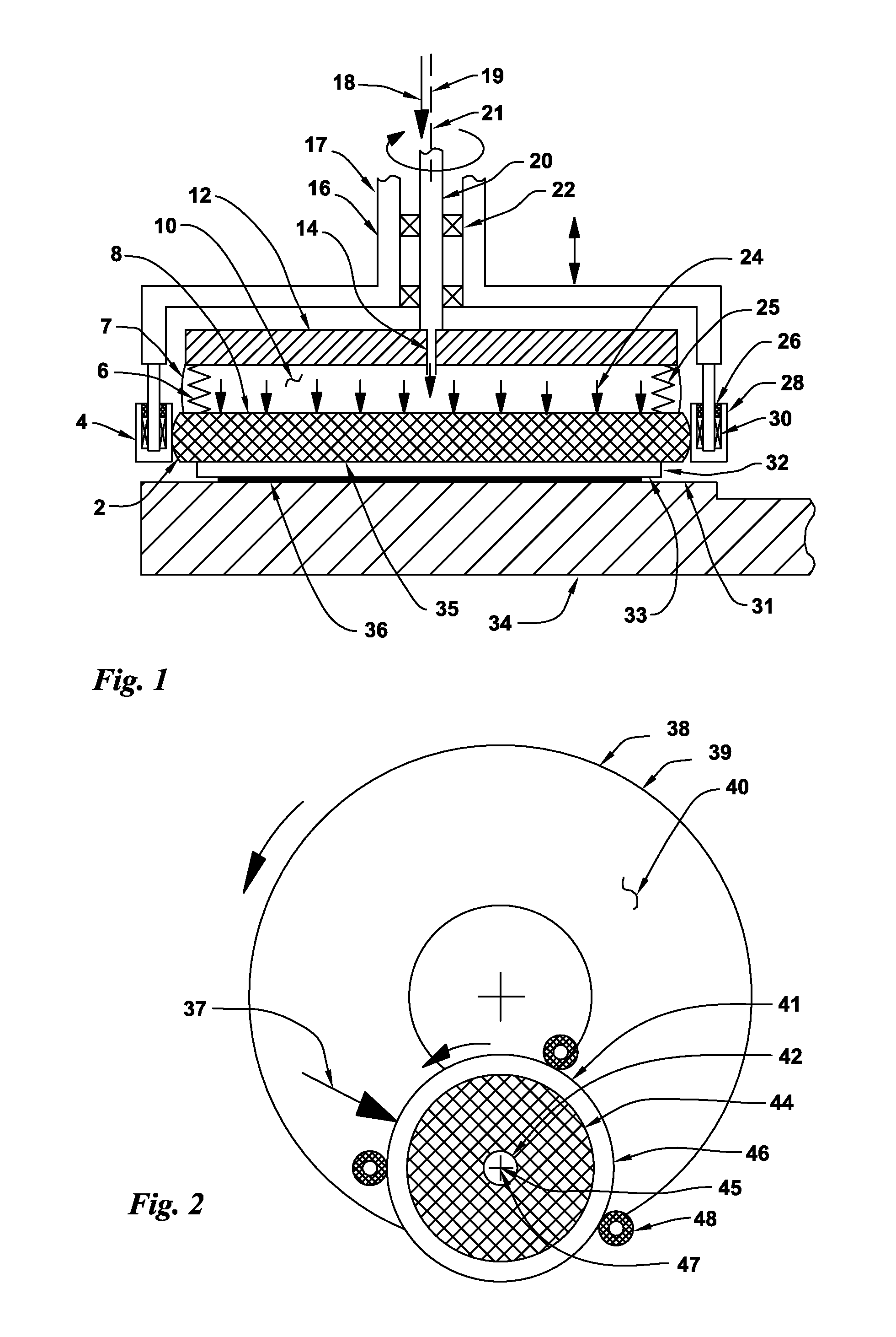
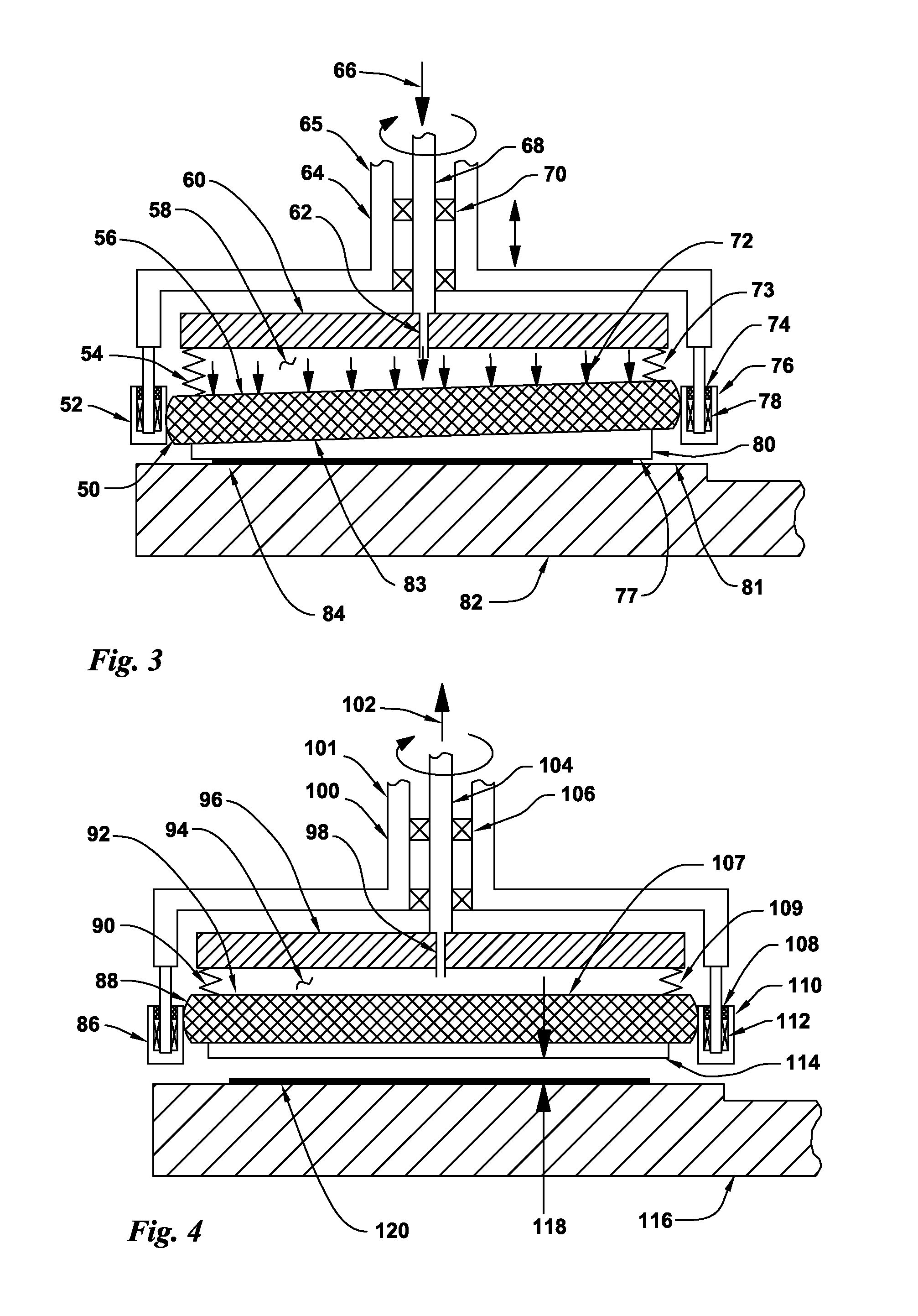
Flat-surfaced workpieces such as semiconductor wafers are attached to a rotatable floating workpiece holder carrier rotor that is supported by and rotationally driven by a bellows. The wafer carrier rotor is contained by a set of idlers that are attached to a stationary rotor housing to provide support against abrading forces that are imposed on the wafer by the moving abrasive coating on a rotary platen. The idlers allow low-friction operation of the abrading system to be provided at the very high abrading speeds used in high speed flat lapping with raised-island abrasive disks. The system is also well suited for lapping optical devices and rotary seals and for chemical mechanical planarization (CMP) polishing of wafers using resilient pads. Pressurized air is injected into the bellows device to provide uniform abrading pressure across the full surface of the wafer. Wafers can be attached to the workpiece carrier with vacuum.

Description

BACKGROUND OF THE INVENTIONField of the Invention[0001]The present invention relates to the field of abrasive treatment of surfaces such as grinding, polishing and lapping. In particular, the present invention relates to a high speed bellow-drive semiconductor wafer workholder system for use with single-sided abrading machines that have rotary abrasive coated flat-surfaced platens. The bellows-drive workholders allow the workpiece substrates to be rotated at the same high rotation speeds as the platens. Often these platen and workholder speeds exceed 3,000 rpm. Conventional workholders can only attain these required rotational speeds with the use of complex devices and operational procedures.[0002]The flexible bellows driven workholders provide that uniform abrading pressures are applied across the full abraded surfaces of the workpieces such as semiconductor wafers. One or more of the workholders can be used simultaneously with a rotary abrading platen.[0003]High speed flat lapping...

Claims


Application Information

Patent Timeline
IPC IPC(8): B24B37/30B24B7/00B24B37/00
CPCB24B37/30
Inventor DUESCHER, WAYNE O.
Owner DUESCHER WAYNE O
Learn More