Device and method for sewage treatment using constant magnetic field

Active Publication Date: 2014-05-22
NANJING UNIV
View PDF6 Cites 5 Cited by
  • Summary
  • Abstract
  • Description
  • Claims
  • Application Information

AI Technical Summary

Benefits of technology

[0010]In view of the above-described problems, it is one objective of the invention to provide a device and a method for sewage treatment using a constant magnetic field that employ an intensified sewage treatment system comprising a magnetic field and microorganisms to improv

Problems solved by technology
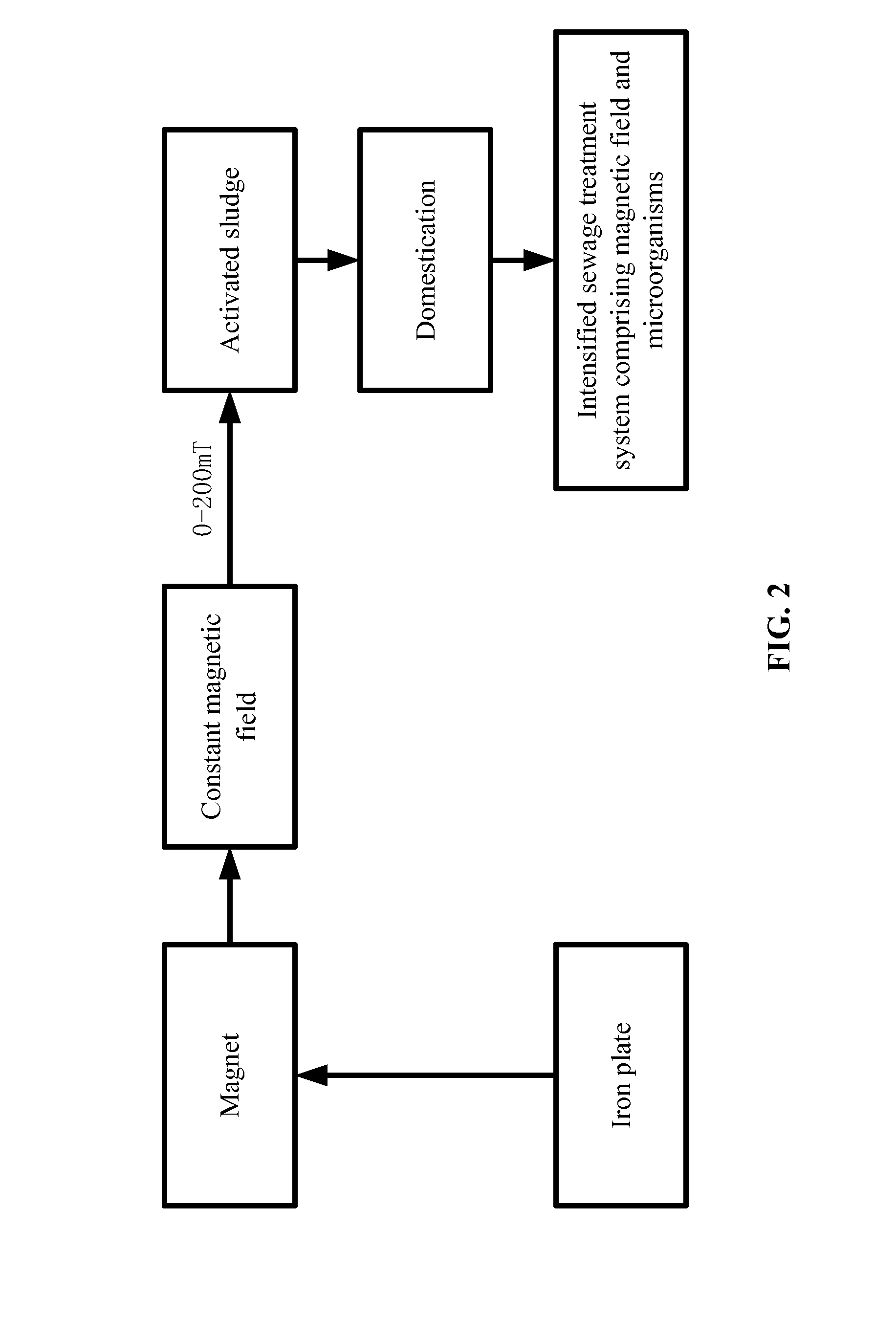
However, as the temperature severely affects the growth, propagation, metabolism, distribution, and the size of biological populations, the efficiency of the sewage treatment plant is low in winter due to low temperature.
However, with the improvement of the sewage treatment standard, effects of the above two methods cannot meet the standard requirements, since the biochemical reaction rate resulting from the weakened metabolism of

Method used


Image

  • Device and method for sewage treatment using constant magnetic field
  • Device and method for sewage treatment using constant magnetic field
  • Device and method for sewage treatment using constant magnetic field

Examples


example 1

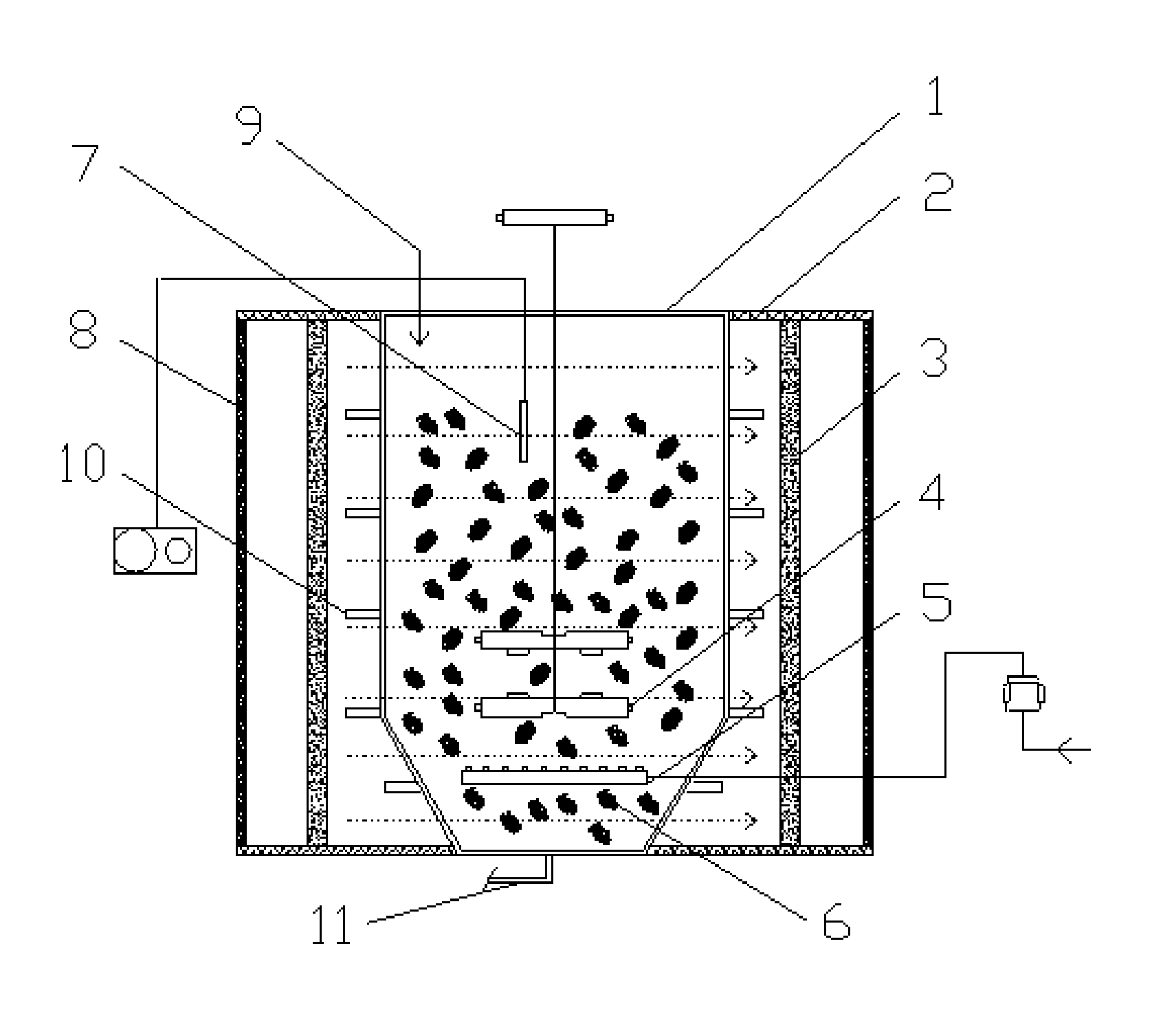
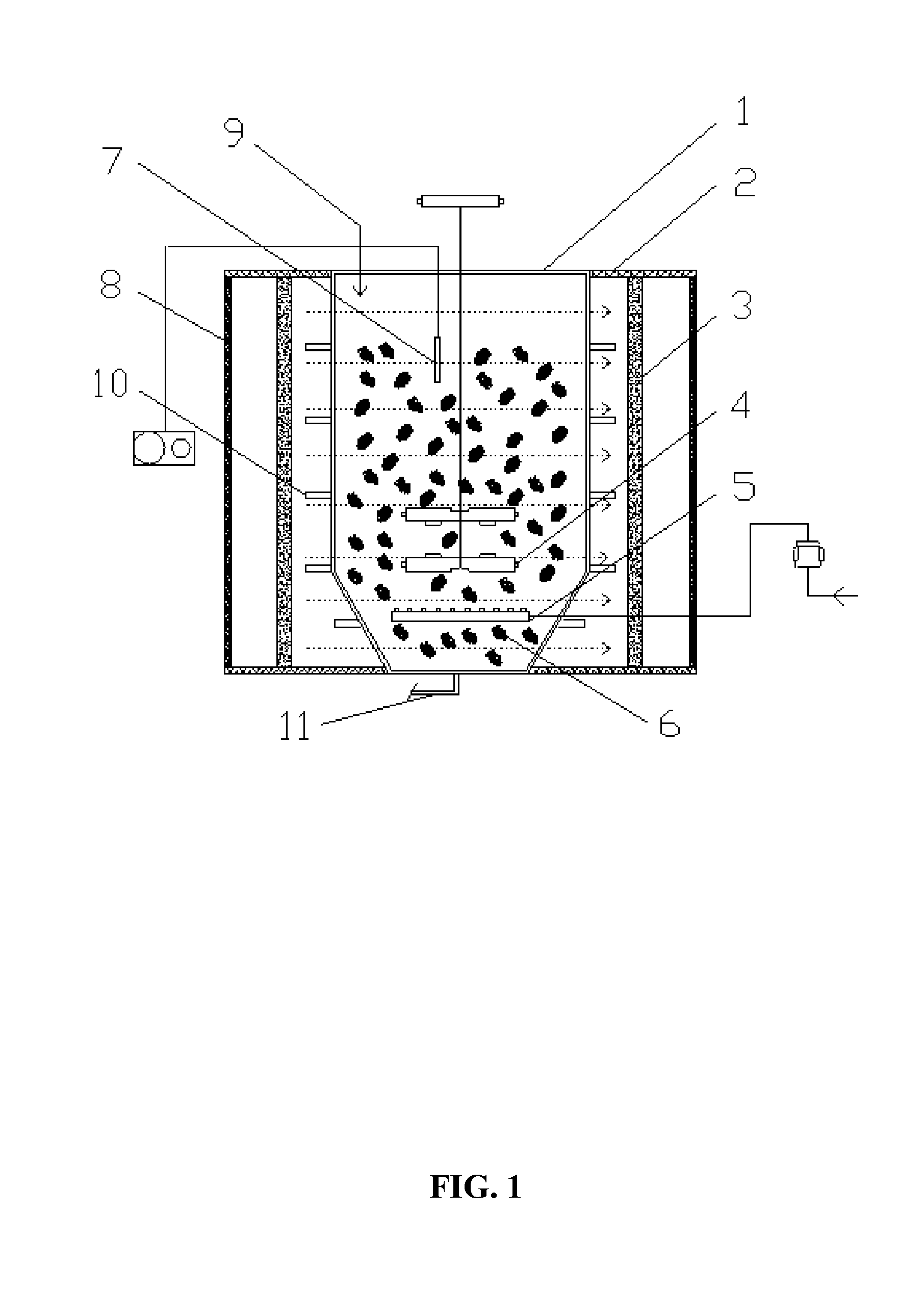
[0032]As shown in FIGS. 1-2, a sewage treatment plant employed a domestic sewage treatment process comprising the following steps:

[0033]a) A reactor 1 having a ratio of height:length:width=2:1:1 was provided. The reactor comprised an activated sludge zone 6, a stirrer 4, an aerator 5, an upper end comprising a water inlet 9, a side wall comprising a water outlet 10, and a bottom comprising a sludge outlet 11. The activated sludge was inoculated at the temperature of 4° C. The activated sludge zone 6 was disposed inside the reactor 1. The stirrer 4 and the aerator 5 were arranged inside the activated sludge zone 6, and the aerator 5 was arranged beneath the stirrer 4. Two ferrite magnets 3 were arranged in parallel on two sides of the reactor 1, an area of each of the ferrite magnets 3 was adjusted to allow the activated sludge zone 6 to be within a range of the magnetic field. Two iron plates 8 having a thickness of 25 mm were arranged outside the ferrite magnets 3, respectively, fo...

example 2

[0038]As shown in FIGS. 1-2, a sewage treatment plant employed a sewage treatment process comprising the following steps:

[0039]a) A reactor 1 having a ratio of height:length:width=4:2:1 was provided. A bottom of the reactor 1 was in a shape of a rectangular. The reactor comprised an activated sludge zone 6, a stirrer 4, an aerator 5, an upper end comprising a water inlet 9, a side wall comprising a water outlet 10, and a bottom comprising a sludge outlet 11. The activated sludge zone 6 was disposed inside the reactor. The stirrer 4 and the aerator 5 were arranged inside the activated sludge zone 6, and the aerator 5 was arranged beneath the stirrer 4. Two ferrite magnets 3 were arranged in parallel on two sides of the reactor 1, an area of each of the ferrite magnets 3 was adjusted to allow the activated sludge zone 6 be within a range of the magnetic field. Two iron plates 8 having a thickness of 50 mm were arranged outside the ferrite magnets 3, respectively, for weakening the mag...

example 3

[0044]The structure of the device for sewage treatment of Example 3 was the same as that in Example 1, except that the magnetic field intensity of the center of the reactor was controlled at 100 mT. The process for sewage treatment comprised the following steps:

[0045]a) At a temperature of 10° C., an activated sludge was filled inside the reactor 1 to form the activated sludge zone 6 in the bottom of the reactor 1. Two magnets 3 was mounted in parallel on two side of the reactor 1 for allowing the magnets 3 to form magnetic fields having the same direction in the reactor 1. An area of each magnet 3 was adjusted to allow the activated sludge zone to be within ranges of the magnetic fields; and iron plates were mounted outside corresponding magnets 3.

[0046]b) A simulated sewage was introduced into the reactor 1. A concentration of the simulated sewage was gradually increased so as to increase an organic load from 0.03 kg / (m3·d) to 0.5 kg / (m3·d) at a constant gradient. Thereafter, the ...


PUM

PropertyMeasurementUnit
Temperatureaaaaaaaaaa
Weightaaaaaaaaaa

Abstract

A device for sewage treatment, including: a reactor and a magnetic field generator. The reactor includes a stirrer, an aerator, an activated sludge zone, an upper end including a water inlet, a side wall including a water outlet, and a bottom including a sludge outlet. The magnetic field includes magnets and iron plates. The activated sludge zone is disposed inside the reactor. The stirrer and the aerator are disposed within the activated sludge zone. The aerator is arranged beneath the stirrer. The magnetic field generator is disposed outside the reactor. The magnets and the iron plates are symmetrically disposed on two sides of the reactor, respectively, and each of the magnets is disposed on the inner side of the corresponding iron plate. The magnets disposed on both sides of the reactor produce magnetic fields having the same direction.

Description

CROSS-REFERENCE TO RELATED APPLICATIONS[0001]Pursuant to 35 U.S.C. §119 and the Paris Convention Treaty, this application claims the benefit of Chinese Patent Application No. 201210475425.9 filed Nov. 22, 2012, the contents of which are incorporated herein by reference. Inquiries from the public to applicants or assignees concerning this document or the related applications should be directed to: Matthias Scholl P.C., Attn.: Dr. Matthias Scholl Esq., 14781 Memorial Drive, Suite 1319, Houston, Tex. 77079.BACKGROUND OF THE INVENTION[0002]1. Field of the Invention[0003]The invention relates to the field of domestic sewage treatment, and more particularly to a device and a method for sewage treatment using a constant magnetic field.[0004]2. Description of the Related Art[0005]Domestic sewage has good biodegradability and high contents of nitrogen and phosphorus, and biochemical methods are often used in domestic sewage treatment. Common methods for domestic sewage treatment include: oxi...

Claims


Application Information

Patent Timeline
IPC IPC(8): C02F3/12
CPCC02F1/482C02F3/12C02F3/121C02F3/1284C02F3/201C02F2209/08Y02W10/10
Inventor REN, HONGQIANGNIU, CHUANGENG, JINJUXU, KE
Owner NANJING UNIV
Why Eureka
Try Eureka