Magnetic sensor using spin transfer torque devices

a technology of magnetic sensor and torque, applied in the direction of measurement device, magnetic measurement, instruments, etc., can solve the problems of limited linearity, heat radiation, complex structure of the structure, etc., and achieve the effect of expanding the dynamic range of the magnetic field, searching, and eliminating hysteresis

Inactive Publication Date: 2014-05-22
KOREA BASIC SCI INST
View PDF9 Cites 8 Cited by
  • Summary
  • Abstract
  • Description
  • Claims
  • Application Information

AI Technical Summary

Benefits of technology

[0018]The advantages of the present invention are as follows:
[0019]First, the coercive field of a magnetic resistance device can be controlled and also hysteresis can be eliminated by controlling the amplitude of a high-frequency current waveform.
[0020]Second, the polarity and strength of even a weak magnetic field of several oersteds emitted from a measurement target can be determined because there is no hysteresis.
[0021]Third, a dynamic range may be freely shifted by con

Problems solved by technology

However, in spite of such higher sensitivity, the spin transfer torque device using STT is problematic in that a measurement range (a dynamic range) is very narrow (about 1 Gauss) and in that there is the dispersion of a switching magnetic field in connection with a manufacturing process and thermal stability.
Furthermore, a coercive field Hc attributable to the hysteresis of a ferromag

Method used


Image

  • Magnetic sensor using spin transfer torque devices
  • Magnetic sensor using spin transfer torque devices
  • Magnetic sensor using spin transfer torque devices

Examples


embodiment 1

4. Embodiment 1

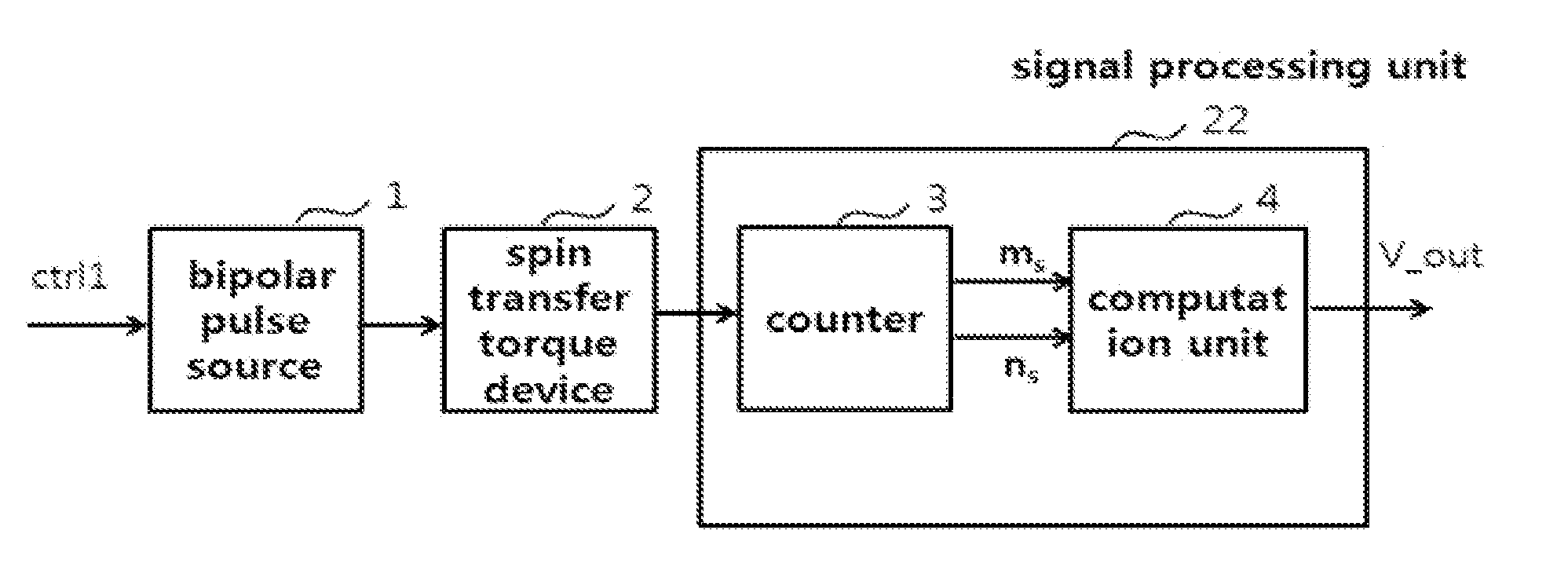
[0054]A method of controlling a coercive field according to the present invention is illustrated in FIG. 6. The magnetic sensor illustrated in FIG. 6 includes a bipolar pulse source 1, a spin transfer torque device 2, and a signal processing unit 22 including a counter 3 and a computation unit 4.

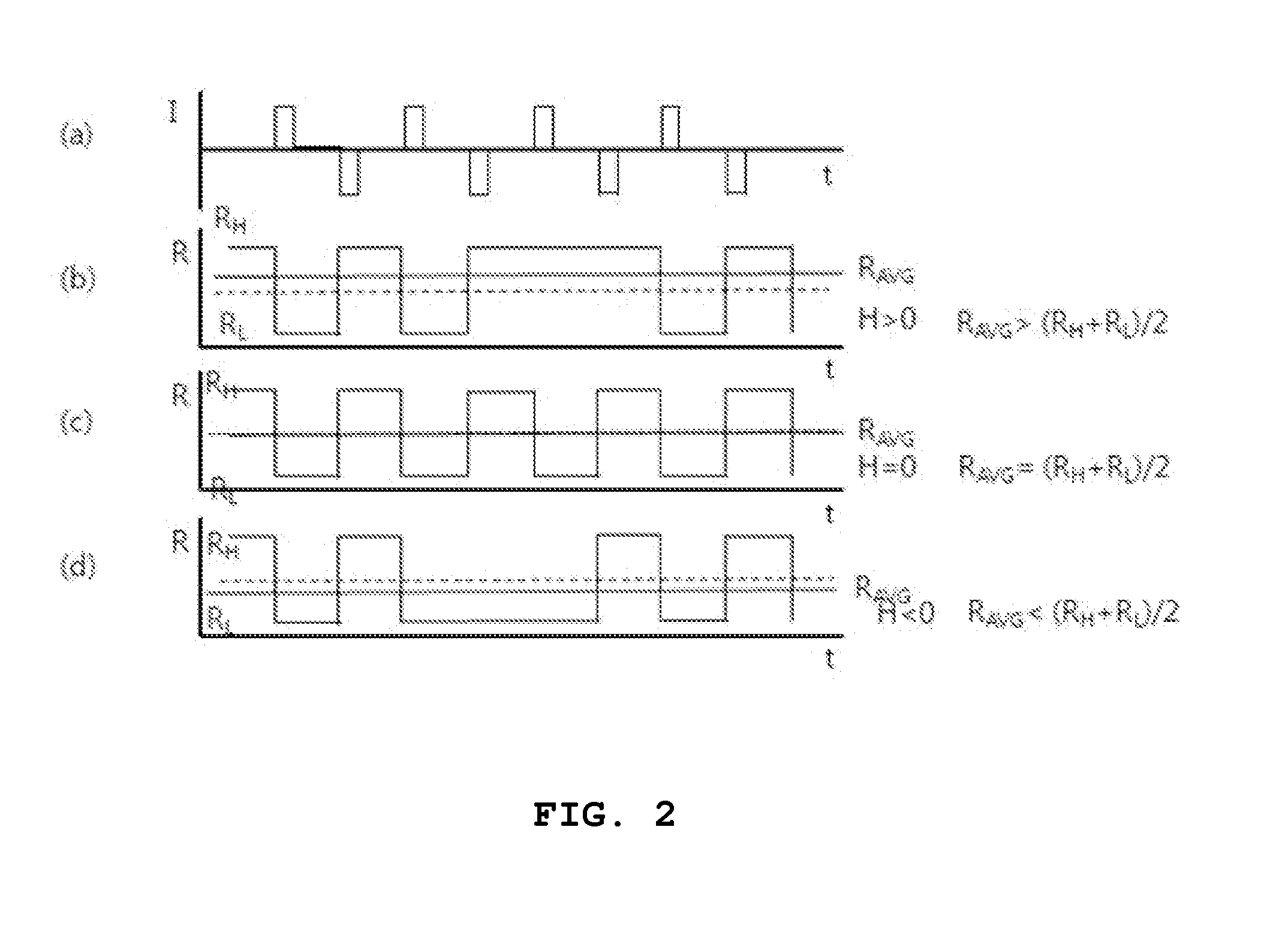
[0055]The bipolar pulse source 1 applies pulses having a positive / negative amplitude directly to the spin transfer torque device 2 in order to cancel out the coercive field of the spin transfer torque device 2, and alternately applies positive / negative pulses. In this case, the shorter the period of the pulses is, the more desirable it is for the linearization of the magnetic sensor. The waveform of the bipolar pulse source 1 may correspond to bipolar sine waves or triangular waves apart from bipolar square waves illustrated in FIG. 2(a). Of the three bipolar waveform examples, bipolar square wave pulses have the lowest power consumption.

[0056]Although the spin transfer torque...

embodiment 2

5. Embodiment 2

[0063]A method of controlling a dynamic range offset according to the present invention is illustrated in FIG. 8. In the magnetic sensor illustrated in FIG. 8, a bias unit 6 capable of applying an offset bias is added to embodiment 1. In the present invention, although the offset of the dynamic range can be controlled by only the offset bias of voltage (current), an exciting wire 7 may be added to extend offset control to a wider region. Furthermore, it may be possible to replace the signal processing unit 22 of FIG. 6 with a low frequency band-pass filter 5. The low frequency band-pass filter performs the function of eliminating high-frequency noise attributable to bipolar pulses and the smoothing function of filtering variations in magnetic resistance value.

[0064]FIG. 9 illustrates an embodiment of the role of an offset bias. When an offset bias is not applied to voltage, a magnetic field proximate to 0 can be detected. When a positive (negative) offset bias is appl...

embodiment 3

6. Embodiment 3

[0066]A method of controlling an output level according to the present invention is illustrated in FIG. 10. A magnetic sensor illustrated in FIG. 10 illustrates that a resistor unit (a resistor network or an attenuator) 8, the resistance level of which is variable, is added in series to a spin transfer torque device 2a. When the magnitude of the resistance is adjusted, the level of an output signal Vout may be determined using the voltage divider rule.

[0067]FIG. 11 illustrates an embodiment in which a spin transfer torque device 2b, instead of the resistor unit 8, has been added in series. The additional spin transfer torque device may be connected in series or parallel, and may vary the level of the output voltage depending on the method of connection. As an example, when the detection direction of a magnetic field of the spin transfer torque device 2b is opposite that of the spin transfer torque device 2a, a push-pull function may be performed.


PUM


Abstract

The present invention is directed to a magnetic sensor using a spin transfer torque device, including a spin transfer torque device configured such that the magnetization direction thereof is varied by current, a bipolar pulse source configured to apply bipolar pulses to the spin transfer torque device in order to control the coercive field and sensitivity of the spin transfer torque device, and a signal processing unit configured to calculate magnetic susceptibility or magnetic resistance by counting the parallel (P) or anti-parallel (AP) states of the spin transfer torque device in response to the applied bipolar pulses.

Description

TECHNICAL FIELD[0001]The present invention relates to a magnetic sensor using spin transfer torque devices and, more particularly, to a magnetic sensor that can respond linearly to the strength of a magnetic field by applying bipolar pulses to a spin transfer torque device and thereby controlling a coercive field.[0002]Furthermore, the present invention relates to a magnetic sensor that can shift a dynamic range by a magnetic field corresponding to an offset bias by applying the offset bias together with bipolar pulses and that can control sensitivity by adjusting the amplitude and strength of bipolar pulses.BACKGROUND ART[0003]A magnetic sensor measures the magnitude or direction of a magnetic field based on a phenomenon in which the magnetic susceptibility or magnetic resistance of a material varies in response to a magnetic field. Generally used magnetic sensors include Hall magnetic sensors using the Hall effect, giant magnetoresistance (GMR) sensors using the GMR phenomenon, tu...

Claims


Application Information

Patent Timeline
IPC IPC(8): G01R33/02
CPCG01R33/02G01R33/0064G01R33/1284G01R33/09
Inventor PARK, SEUNG YOUNGKIM, SANG II
Owner KOREA BASIC SCI INST
Why Eureka
Try Eureka