Common mode noise cancellation circuit for unbalanced signals

Active Publication Date: 2014-05-22
C-MEDIA ELECTRONICS INC
View PDF0 Cites 5 Cited by
  • Summary
  • Abstract
  • Description
  • Claims
  • Application Information

AI Technical Summary

Benefits of technology

[0010]An exemplary embodiment of the present disclosure provides a common mode noise cancellation ci

Problems solved by technology

Interference caused by common mode noise is a common issue in an electronic system.
Interference caused by the common mode noise is likely to have a negative impact on a signal and a system, such as downgrading signal quality and system performance.
However, if interference caused by the common mode noise occurs in an unbalanced signal system, meaning the signal and the grounding are both interfered simultaneously.
In this case, interferences on both terminals are difficult to be removed.
The signal to noise ratio (SNR) of such system will get worse.
However, if the noise frequency is low, the common mode choke is almost invalid to reduce the noise since impedance of an inductive component such as the common mode choke is very low in low frequency.
For example if the common mode noise is within the audio band, it is very difficult to remove the noise with common mode choke.
Further, since common mode noise for unbalanced signals is not an easy issue to be solved, a conventional solution is to convert the unbalanced signal to a balanced or said fully differential signals during signal processing.
Such process, however, can be complex and costly.
Hence interference caused by common mode noise, especially in low frequency, is a problem which is

Method used


Image

  • Common mode noise cancellation circuit for unbalanced signals
  • Common mode noise cancellation circuit for unbalanced signals
  • Common mode noise cancellation circuit for unbalanced signals

Examples


Embodiment Construction

[0020]Reference will now be made in detail to the exemplary embodiments of the present disclosure, examples of which are illustrated in the accompanying drawings. Wherever possible, the same reference numbers are used in the drawings and the description to refer to the same or like parts.

[0021][Embodiment of a Common Mode Noise Cancellation Circuit for an Unbalanced Signals]

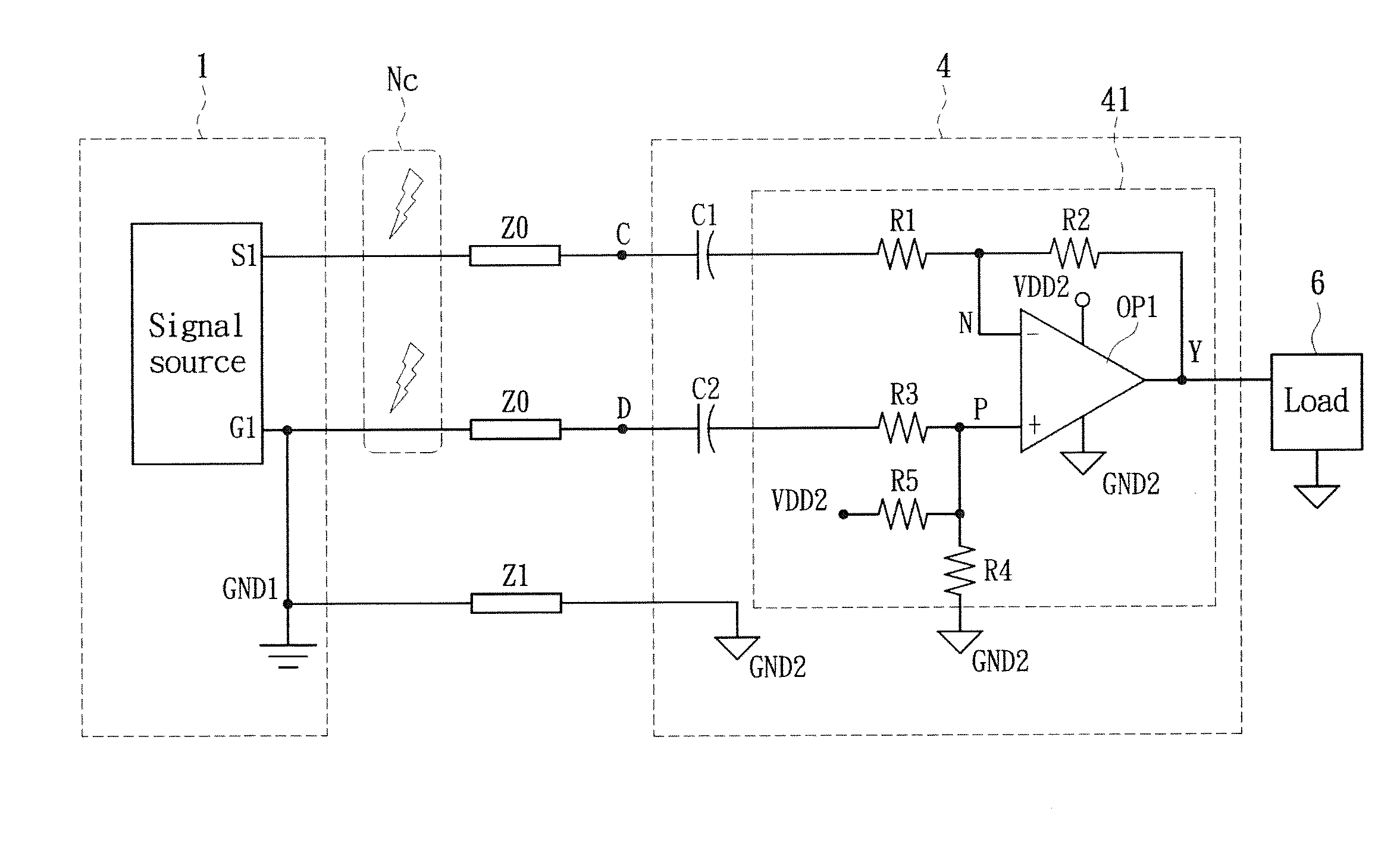
[0022]Please refer to FIG. 3. FIG. 3 is a diagram illustrating a common mode noise cancellation circuit 4 for the unbalanced signals according to an embodiment of the present disclosure. The unbalanced signals are from a first signal terminal S1 and a second signal terminal G1 of a signal source 1. The second signal terminal G1 is coupled to a grounding terminal GND1 and possesses a first grounding potential. The unbalanced signals can be any signals that are single-ended and referenced to ground. The common mode noise cancellation circuit 4 comprises the grounding terminal GND1 and a subtractor 41.

[0023]The grou...


PUM


Abstract

This invention provides a common mode noise cancellation circuit for the unbalanced signals. The unbalanced signals come from a signal source with a first signal terminal and a second signal terminal having a first grounding potential. The common mode noise cancellation circuit comprises a grounding terminal and a subtractor. The grounding terminal with a second grounding potential is electrically coupled to the second signal terminal of the signal source through an impedance unit. The subtractor comprises a first receiving terminal, a second receiving terminal and a signal output terminal. The first receiving terminal and the second receiving terminal are electrically coupled to the first signal terminal and the second signal terminal respectively for receiving the unbalanced signals. The subtractor subtracts the noise coming from the first receiving terminal and the noise coming from the second receiving terminal to reduce the output noise of the signal output terminal.

Description

BACKGROUND[0001]1. Technical Field[0002]The present disclosure relates to a common mode noise cancellation circuit, in particular, to the common mode noise cancellation circuit for unbalanced signals.[0003]2. Description of Related Art[0004]Interference caused by common mode noise is a common issue in an electronic system. Such, phenomenon occurs when a positive / negative terminal and grounding of a signal are interfered with the same noise. Interference caused by the common mode noise is likely to have a negative impact on a signal and a system, such as downgrading signal quality and system performance. A conventional solution to common mode noise interference is to utilize fully differential signals, so as to eliminate the noise by subtracting the positive terminal with the negative terminal of the interfered signal. However, if interference caused by the common mode noise occurs in an unbalanced signal system, meaning the signal and the grounding are both interfered simultaneously...

Claims


Application Information

Patent Timeline
IPC IPC(8): H03L9/00
CPCH03F3/45928
Inventor SHIEH, WEN-LUNGHUANG, CHIH-YING
Owner C-MEDIA ELECTRONICS INC
Why Eureka
Try Eureka