Power conversion apparatus with low common mode noise and application systems thereof

low common mode noise technology, applied in power conversion systems, ac-ac conversion, circuit arrangements, etc., can solve the problems of high voltage change rate (dv/dt) and high current change rate (di/dt), common mode noise, etc., to reduce the overall cost reduce the size of the common mode filter inductor, and suppress the common mode noise of a power conversion apparatus

Active Publication Date: 2014-05-22
DELTA ELECTRONICS INC
View PDF9 Cites 41 Cited by
  • Summary
  • Abstract
  • Description
  • Claims
  • Application Information

AI Technical Summary

Benefits of technology

[0015]According to the present application, the power conversion apparatus is capable of suppressing common mode noise of a power conversion apparatus effectively, or facilitat

Problems solved by technology

Switching operations of switching elements of a power conversion apparatus may cause a high voltage change rate (dv/dt) and a high current change rate (di/dt).
A rapid change of a voltage and a rapid change of a current may cause common mode noise through a distributed capacitance between a system and the ground.
The common mode noise flows into a grid, which will interfere with other electronic devices connected to the grid.
Potential jumping of the DC bus midpoint O as well as the midpoints of the bridge arms A, B and C relative to the ground may cause displacement current through the aforementioned stray capacitances C0, C1a, C1b and C1c, and the displacement current

Method used


Image

  • Power conversion apparatus with low common mode noise and application systems thereof
  • Power conversion apparatus with low common mode noise and application systems thereof
  • Power conversion apparatus with low common mode noise and application systems thereof

Examples


Embodiment Construction

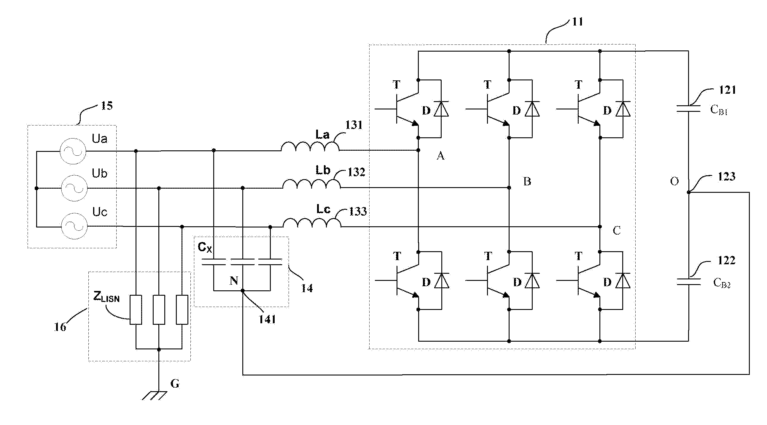
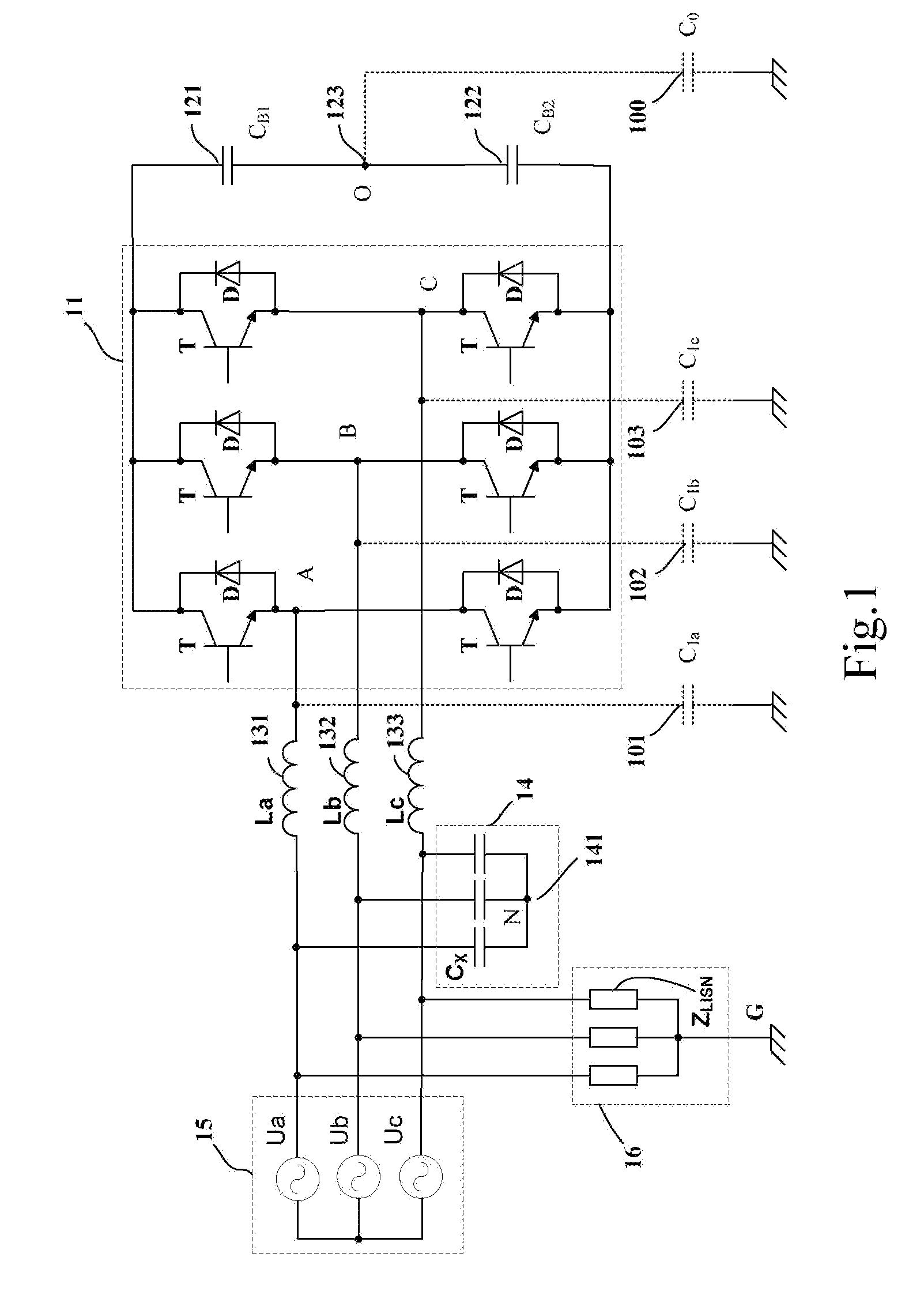
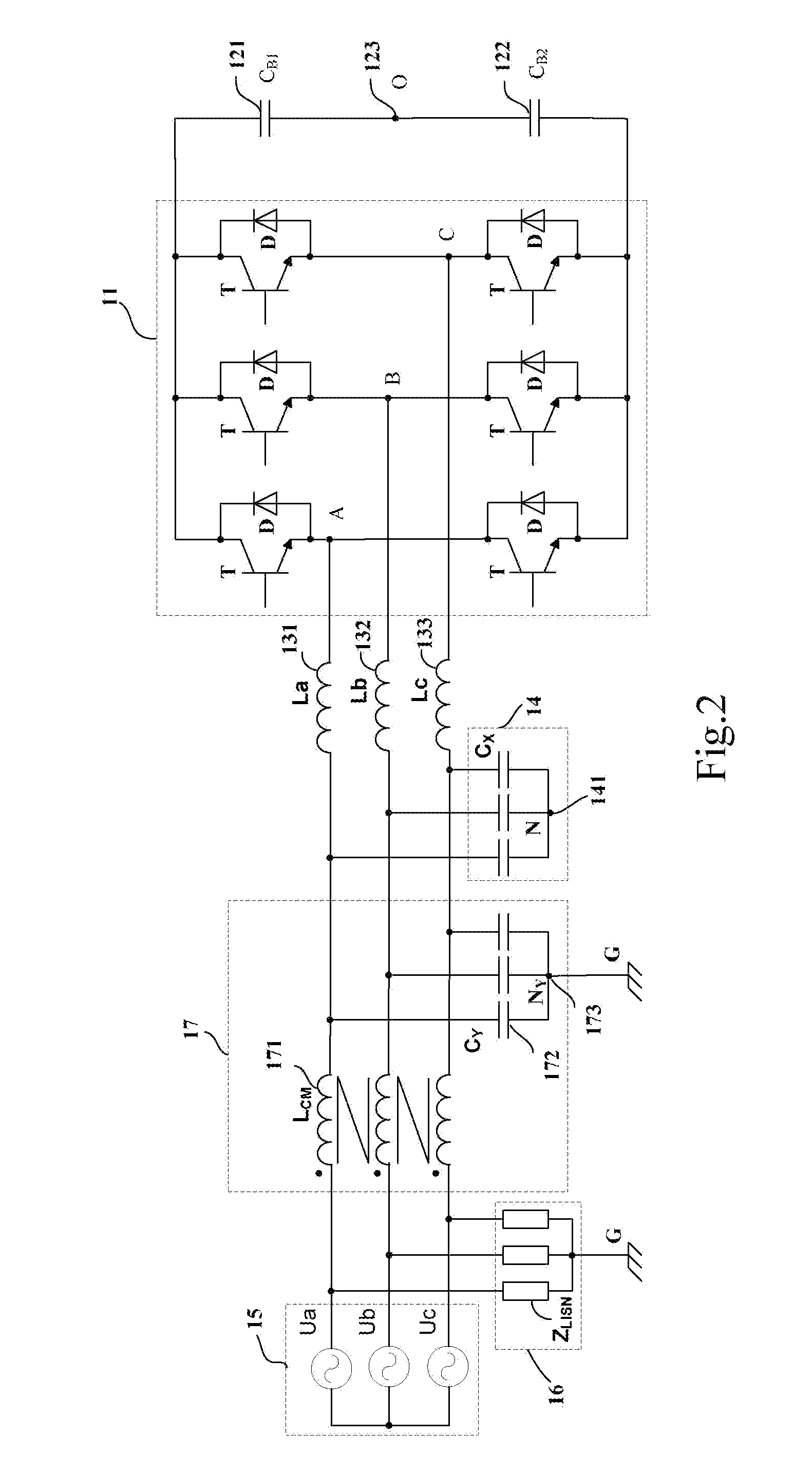
[0040]The present application will be described with reference to FIGS. 5 to 13C. It shall be noted that, in the following illustrated drawings of the present application, elements having the same reference numbers in systems have the same function; if there exists crossing between line segments serving as connecting wires, the crossing labeled with a black spot “•” indicates that the crossing labeled is a connection point, the crossing labeled with no black spots “•” indicates that the crossing labeled is not a connection point but merely crossing over; turns of respective coils are only for illustration purposes, but not indicate the number of actual turns or turn ratio; reference signs of every inductor, transformer coil and capacitor not only indicate these elements themselves, but also indicate algebraic signs indicating the volume or value of these elements.

[0041]In FIG. 3, a common terminal N (141) of the star-connected X capacitor bank 14 is directly connected to the DC bus ...


PUM


Abstract

A power conversion apparatus, comprising: a power conversion circuit comprising an AC source; a power conversion unit with DC terminals and AC terminals; a filter inductor unit including first and second terminals, the first terminals of the filter inductor unit being connected to the AC source, the second terminals of the filter inductor unit being connected to the AC terminals of the power conversion unit; a common mode noise suppression circuit comprising a capacitive impedance network including first and second terminals; an impedance balancing network including first and second terminals; the second terminals of the capacitive impedance network are connected to the first terminals of the impedance balancing network, the first terminals of the capacitive impedance network are connected to the first terminals of the filter inductor unit, and the second terminals of the impedance balancing network are connected to the DC terminals of the power conversion unit.

Description

CROSS-REFERENCE TO RELATED APPLICATIONS[0001]The present application claims priority under 35 U.S.C. §119 to Chinese Patent Application No. 201210464340, filed on Nov. 16, 2012, the entire contents of which are incorporated herein by reference.TECHNICAL FIELD[0002]The present application relates to a power conversion apparatus, and an energy conversion system, a transducer drive system, an active power filter and a solar grid inverter system using such a power conversion apparatus.BACKGROUND[0003]Switching operations of switching elements of a power conversion apparatus may cause a high voltage change rate (dv / dt) and a high current change rate (di / dt). A rapid change of a voltage and a rapid change of a current may cause common mode noise through a distributed capacitance between a system and the ground. The common mode noise flows into a grid, which will interfere with other electronic devices connected to the grid.[0004]FIG. 1 illustratively shows a circuit diagram of a typical t...

Claims


Application Information

Patent Timeline
IPC IPC(8): H02M1/12
CPCH02M1/126H02M1/123H02M1/12H02M5/4585H02M7/217H02M7/5387
Inventor ZHOU, JINPINGZHOU, MINXIE, YICONG
Owner DELTA ELECTRONICS INC
Why Eureka
Try Eureka