
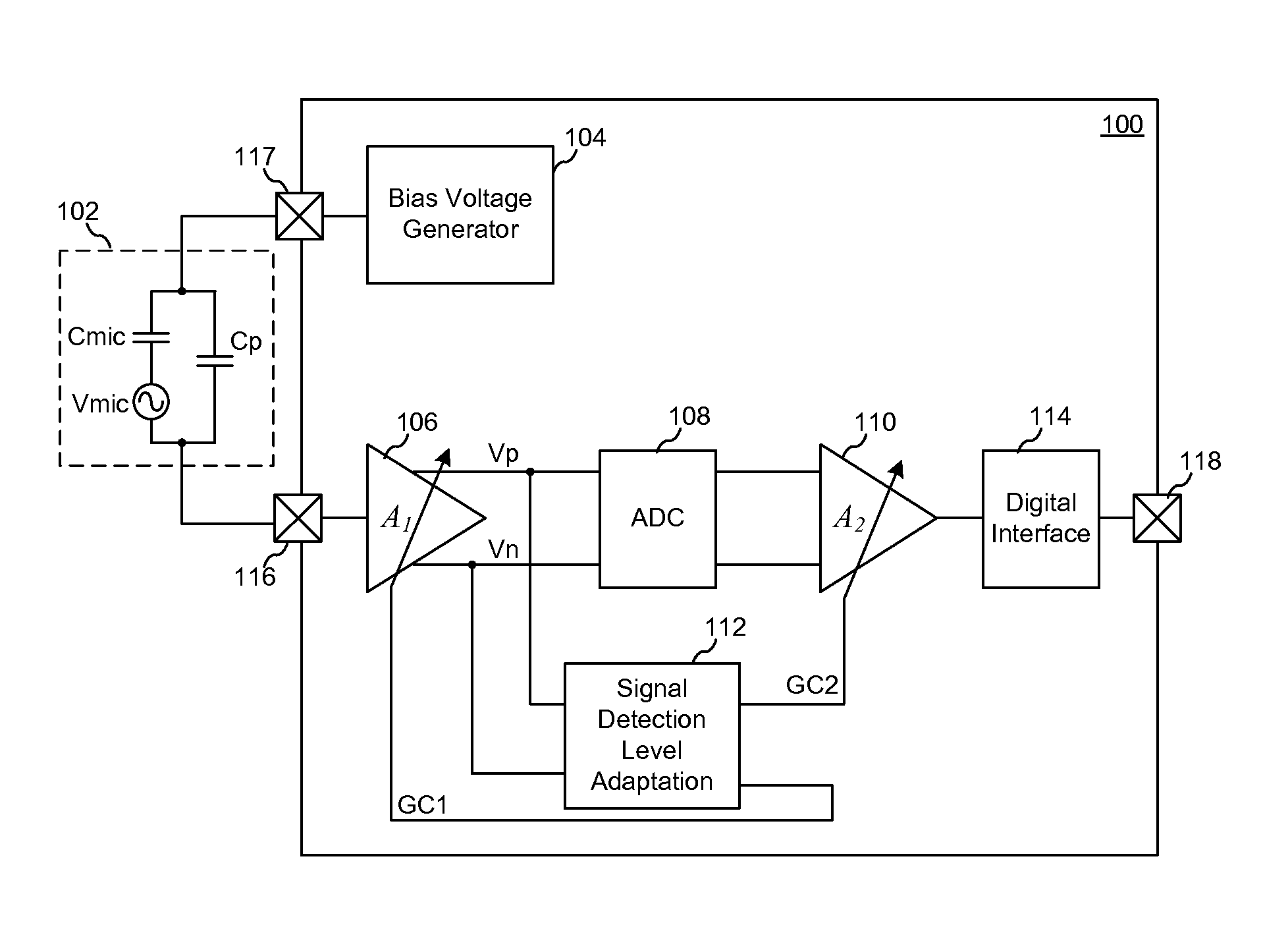
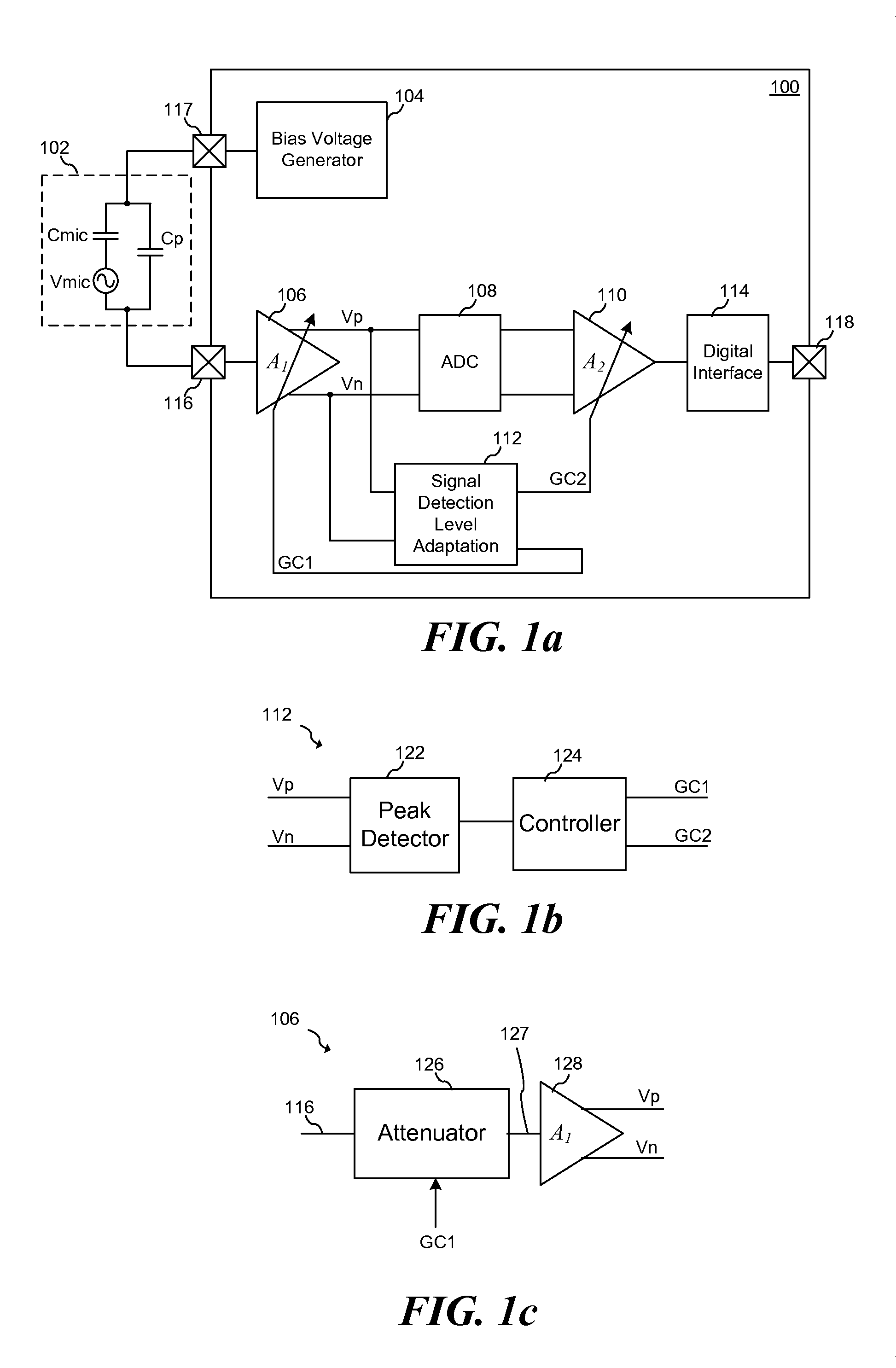
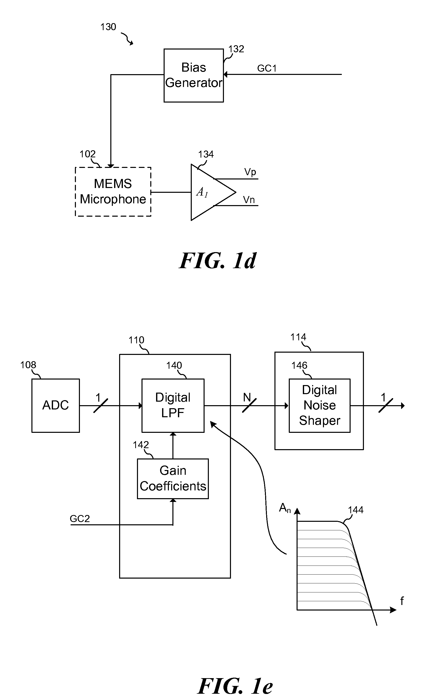
System and Method for High Input Capacitive Signal Amplifier

a capacitive signal and amplifier technology, applied in the direction of digital/coded signal control, volume compression/expansion having semiconductor devices, pulse technique, etc., can solve the problems of not being able to handle the full audio range without significant distortion, and dealing with such high-level signals poses some difficulties

Active Publication Date: 2014-05-22
INFINEON TECH AG
View PDF14 Cites 32 Cited by
  • Summary
  • Abstract
  • Description
  • Claims
  • Application Information

AI Technical Summary

Benefits of technology

This approach allows for the handling of high acoustic signals up to 140 dB SPL with total harmonic distortion below 10%, maintaining sensitivity over a wide range and optimizing noise performance at lower input levels.

Problems solved by technology

While the diaphragm of a microphone, such as a MEMS microphone, may be able to withstand high intensity acoustic signals and faithfully convert these high intensity acoustic signals into an electronic signal, dealing with such high-level signals poses some difficulties.
As such, these systems may not be able to handle the full audio range without adding significant distortion.

Method used


Image

  • System and Method for High Input Capacitive Signal Amplifier
  • System and Method for High Input Capacitive Signal Amplifier
  • System and Method for High Input Capacitive Signal Amplifier

Examples


Embodiment Construction

[0014]The making and using of the presently preferred embodiments are discussed in detail below. It should be appreciated, however, that the present invention provides many applicable inventive concepts that can be embodied in a wide variety of specific contexts. The specific embodiments discussed are merely illustrative of specific ways to make and use the invention, and do not limit the scope of the invention.

[0015]The present invention will be described with respect to embodiments in a specific context, namely an amplifier for a capacitive signal source such as a MEMS or an electret condenser microphone (ECM). The invention may also be applied, however, to other types of circuits and systems, such as audio systems, communication systems, sensor systems and other systems that interface to high impedance signal sources.

[0016]In an embodiment, an amplifier maintains a large dynamic range of a capacitive signal source, such as a microphone, by compressing the output signal of the cap...


PUM


Abstract

In accordance with an embodiment, a method includes determining an amplitude of an input signal provided by a capacitive signal source, compressing the input signal in an analog domain to form a compressed analog signal based on the determined amplitude, converting the compressed analog signal to a compressed digital signal, and decompressing the digital signal in a digital domain to form a decompressed digital signal. In an embodiment, compressing the analog signal includes adjusting a first gain of an amplifier coupled to the capacitive signal source, and decompressing the digital signal comprises adjusting a second gain of a digital processing block.

Description

[0001]This application claims the benefit of U.S. Non-Provisional application Ser. No. 13 / 447,792, filed on Apr. 16, 2012, which application is hereby incorporated herein by reference in its entirety.TECHNICAL FIELD[0002]This invention relates generally to semiconductor circuits and methods, and more particularly to an amplifier for a low distortion capacitive signal source.BACKGROUND[0003]Audio microphones are commonly used in a variety of consumer applications such as cellular telephones, digital audio recorders, personal computers and teleconferencing systems. In particular, lower-cost electret condenser microphones (ECM) are used in mass produced cost sensitive applications. An ECM microphone typically includes a film of electret material that is mounted in a small package having a sound port and electrical output terminals. The electret material is adhered to a diaphragm or makes up the diaphragm itself. Most ECM microphones also include a preamplifier that can be interfaced to...

Claims


Application Information

Patent Timeline
Patent Type & Authority Applications(United States)
IPC IPC(8): H03G3/00H04R3/00H04R23/00
CPCH03F1/3211H03F3/187H03F3/45475H03G7/002H03G7/06H03F2203/45166H03F2203/45526H04R2201/003H03K5/1532H03K5/1536H03F1/38H03F1/56H03F3/2175H04R19/04H03G3/002H04R3/00H04R23/00H03F2200/555H03G3/3005H03G3/3089H03G7/08
Inventor KROPFITSCH, MICHAELCEBALLOS, JOSE LUIS
Owner INFINEON TECH AG
Learn More