Packaged Chip For Multiplexing Photonic Crystal Microcavity Coupled Waveguide And Photonic Crystal Slot Waveguide Devices For Chip-Integrated Label-Free Detection And Absorption Spectroscopy With High Throughput, Sensitivity, Specificity, And Wide Dynamic Range

a technology of photonic crystal microcavity and integrated optical devices, which is applied in the direction of optical waveguide light guides, optical elements, instruments, etc., can solve the problems of small wavelength range over which light is slowed down as it propagates down the photonic crystal waveguide, and achieves a small minimize reflection, and reduce the effect of effective refractive index or dielectric constan

Active Publication Date: 2014-05-22
OMEGA OPTICS
View PDF0 Cites 44 Cited by
  • Summary
  • Abstract
  • Description
  • Claims
  • Application Information

AI Technical Summary

Benefits of technology

[0010]Signal amplification as well as specific detection is achieved at low concentrations by incorporating a sandwich immunoassay technique. The target receptor molecule that is bound to the microcavity surface is designated as a primary target receptor. A resonance wavelength shift occurs when a probe biomolecule attaches to the primary target receptor. A secondary target biomolecule which also binds specifically to the probe biomolecule, when introduced, now causes an additional secondary resonance wavelength shift. In this way, the secondary target verifies that the biomolecule that has bound to the primary target receptor is in fact the probe biomolecule. By monitoring the resonance wavelength shifts, the specificity of binding is confirmed. No resonance wavelength shift shall be observed upon introduction of either the probe biomolecule or the secondary target antibodies, on a second photonic crystal microcavity in the array which is coated with a control biomolecule such as bovine serum albumin (BSA). No resonance wavelength shift shall be observed upon introduction of either the probe biomolecule or the secondary target antibodies, on a third photonic crystal microcavity in the array which is coated with an isotype matched control biomolecule. The specificity of the assay is thus verified from the results on three photonic crystal microcavities. In addition to the secondary resonance wavelength shift caused by the binding of the secondary target to the probe biomolecule, the lack of any resonance wavelength shift in the control photonic crystal microcavities confirms the specificity. In one preferred embodiment, more than one photonic crystal microcavity is coated with the same primary target receptor. At the same time, more than one photonic crystal microcavity is coated separately with the same or different control biomolecule or isotype matched control to the primary target receptor. Specificity is thus justified by the simultaneous binding and none thereof in the multiplexed sandwich arrangement. The secondary target that binds to the primary probe biomolecule adds to the primary resonance wavelength shift of the probe biomolecule to the primary target receptor, thereby leading to signal amplification for enhanced device sensitivity.
[0027]The third objective of the invention is to use crossing optical waveguides primarily from a mechanical perspective, in preventing the leakage of fluids from the microfluidic channels. The crossing optical waveguides at the same time do not result in any significant optical loss and thus preserve the original device characteristics as those without crossing waveguides.

Problems solved by technology

However, in a photonic crystal slot waveguide, the wavelength range over which light is slowed down as it propagates down the photonic crystal waveguide is small.
The washing steps are completed in a few seconds, which ensures that unbound target Abs do not have sufficient time to bind to undesired areas which would result in cross-talk.

Method used


Image

  • Packaged Chip For Multiplexing Photonic Crystal Microcavity Coupled Waveguide And Photonic Crystal Slot Waveguide Devices For Chip-Integrated Label-Free Detection And Absorption Spectroscopy With High Throughput, Sensitivity, Specificity, And Wide Dynamic Range
  • Packaged Chip For Multiplexing Photonic Crystal Microcavity Coupled Waveguide And Photonic Crystal Slot Waveguide Devices For Chip-Integrated Label-Free Detection And Absorption Spectroscopy With High Throughput, Sensitivity, Specificity, And Wide Dynamic Range
  • Packaged Chip For Multiplexing Photonic Crystal Microcavity Coupled Waveguide And Photonic Crystal Slot Waveguide Devices For Chip-Integrated Label-Free Detection And Absorption Spectroscopy With High Throughput, Sensitivity, Specificity, And Wide Dynamic Range

Examples


second embodiment

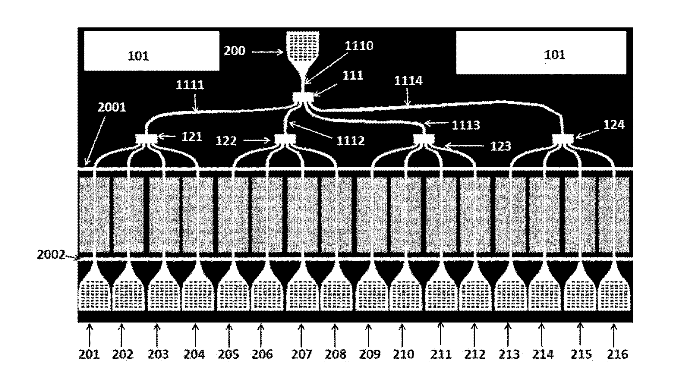
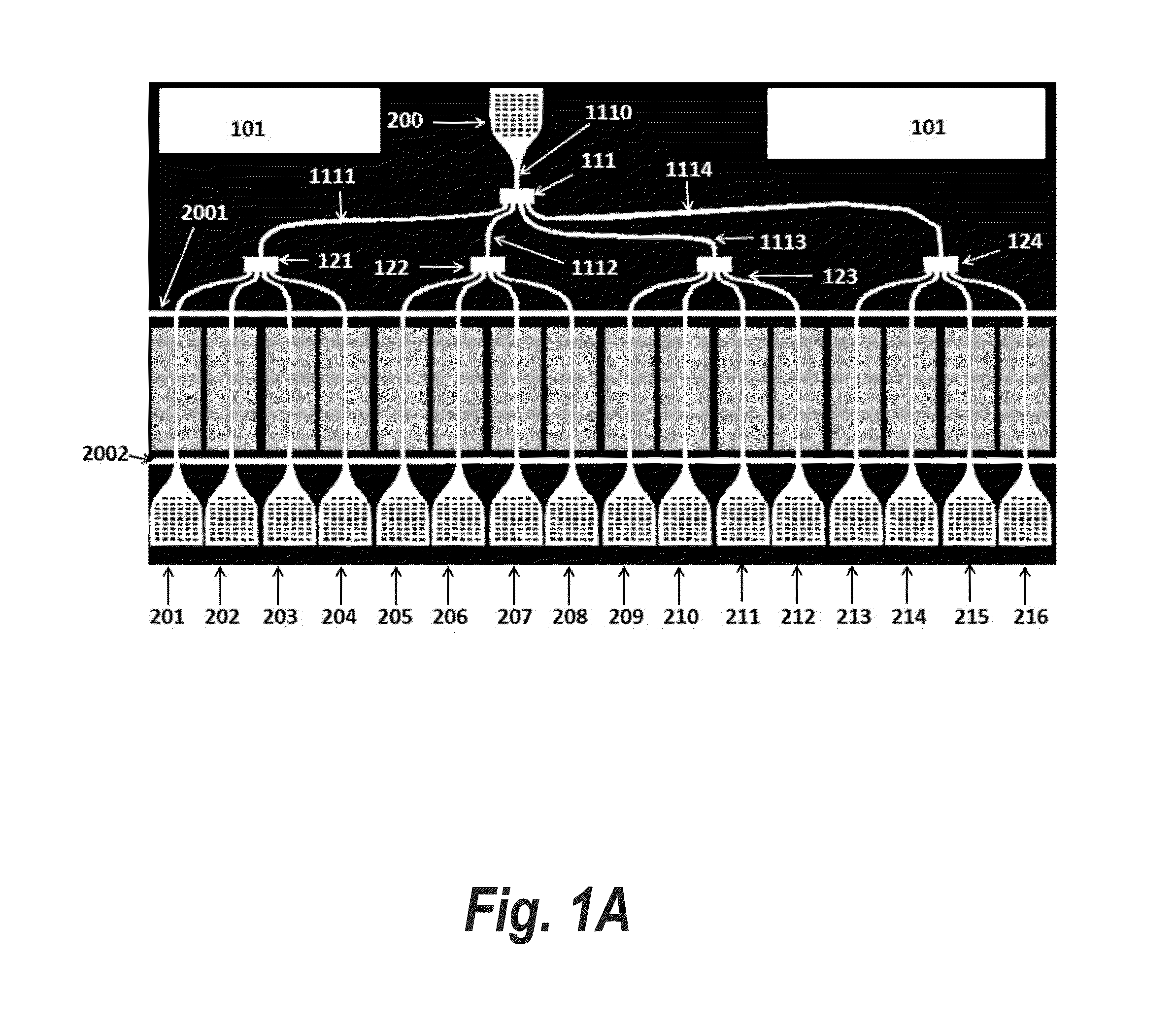
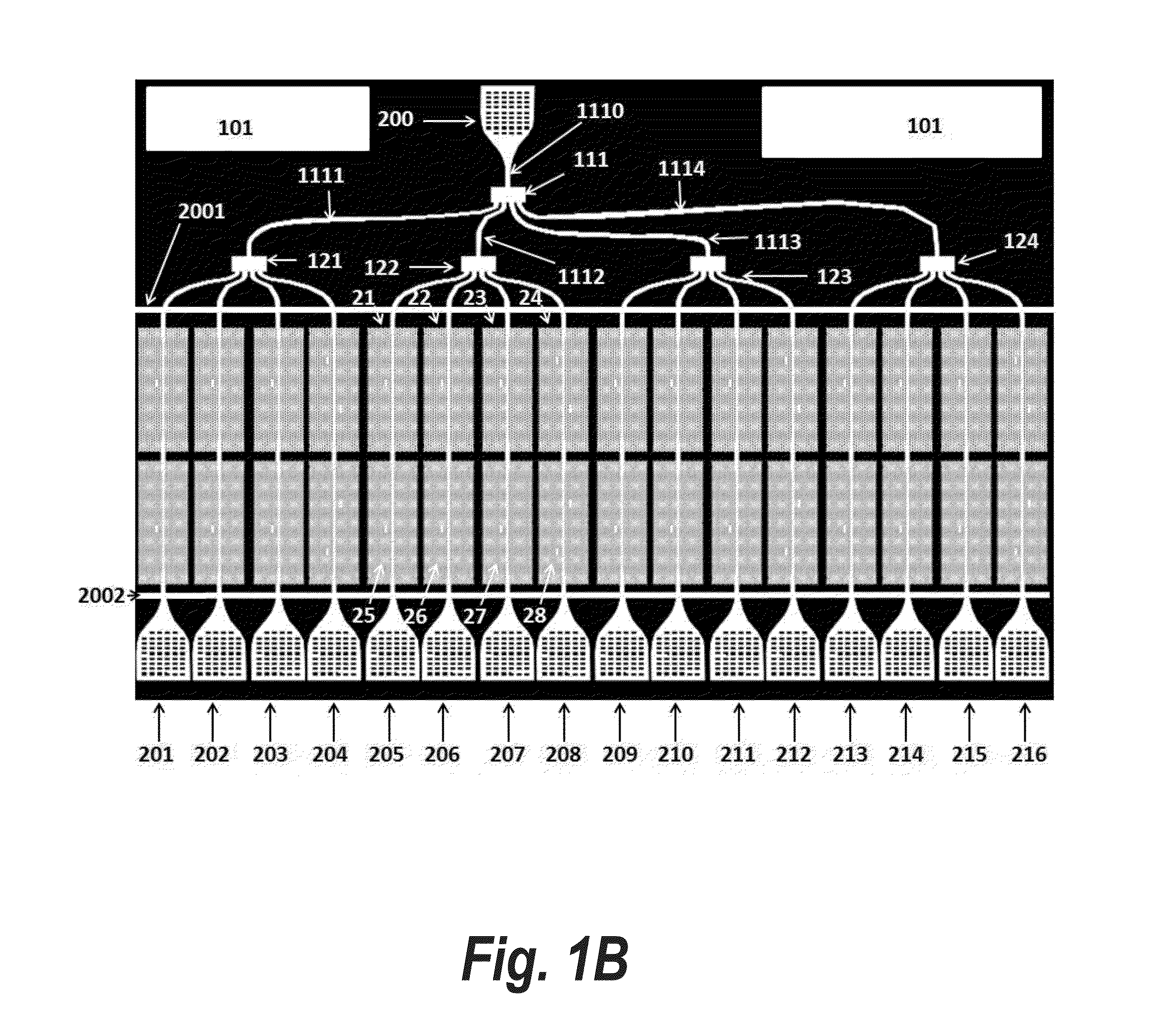
[0112]FIG. 18A is the top view of the packaged optical chip showing the layout of the chip in FIG. 1A in the package 600. Square grooves 601, 602, 603, and 604 are made at the four corners of the package. The package 600 may be ceramic, plastic, or any material which provides toughness and environmental protection to the internal semiconductor chip. The opening in the package 701 on the top side is aligned with the microfluidic channel opening 700 in the semiconductor chip. Openings are made in the package 600 as bordered by the segments 1071 and 1072. The element 109 is also voided in the region bordered by 1071 and 1072 so that the element 108 is exposed. In essence, light is then coupled into the semiconductor chip from the top of the chip from external optical sources and through the top cover polymer cover 108. Similarly, light is coupled out of the semiconductor chip from the top of the chip to external optical detectors and through the top cover polymer cover 108.

[0113]FIG. 1...

third embodiment

[0116]FIG. 20 is the top view of the packaged optical chip showing the layout of the chip in FIG. 1A in the package 600. Square grooves 601, 602, 603, and 604 are made at the four corners of the package. The package 600 may be ceramic, plastic, or any material which provides toughness and environmental protection to the internal semiconductor chip. The opening in the package 701 on the top side is aligned with the microfluidic channel opening 700 in the semiconductor chip. Openings are made in the package 600 as bordered by the segments 1071 and 1072. The elements 108 and 109 are also voided in the region bordered by 1071 and 1072 so that the input sub-wavelength grating coupler 200 and the output sub-wavelength grating couplers 201, 202, 203 . . . 216 are exposed. In essence, light is then coupled into the semiconductor chip from the top of the chip from external optical sources and directly into the input sub-wavelength grating coupler 200. Similarly, light is coupled out of the s...


PUM


Abstract

Systems and methods for chip-integrated label-free detection and absorption spectroscopy with high throughput, sensitivity, and specificity are disclosed. The invention comprises packaged chips for multiplexing photonic crystal microcavity waveguide and photonic crystal slot waveguide devices. The packaged chips comprise crossing waveguides to prevent leakage of fluids from the microfluidic channels from the trenches or voids around the light guiding waveguides. Other embodiments are described and claimed.

Description

I. CROSS REFERENCE TO RELATED APPLICATIONS[0001]The application is a continuation-in-part application of U.S. patent application Ser. No. 13 / 607,801, titled “Packaged Chip for Multiplexing Photonic Crystal Waveguide and Photonic Crystal Slot Waveguide Devices for Chip-Integrated Label-Free Detection and Absorption Spectroscopy with High Throughput, Sensitivity, and Specificity”, filed Sep. 9, 2012, which is a continuation-in-part application of U.S. patent application Ser. No. 12 / 462,311, titled “Photonic Crystal Microarray Device for Label-Free Multiple Analyte Sensing, Biosensing and Diagnostic Assay Chips”, filed Aug. 3, 2009, now U.S. Pat. No. 8,293,177 and a continuation-in-part application of U.S. patent application Ser. No. 12 / 806,840, titled “Photonic Crystal Slot Waveguide Miniature On-Chip Absorption Spectrometer”, filed Aug. 23, 2010, now U.S. Pat. No. 8,282,882, the contents of which are all hereby incorporated by reference.II. BACKGROUND[0002]1. Field of the Invention[0...

Claims


Application Information

Patent Timeline
Patent Type & Authority Applications(United States)
IPC IPC(8): G02B6/12
CPCG02B6/12004G01N21/253B82Y20/00G01N21/7746G01N33/54373G01N2021/7789G02B6/1225G02B6/124G02B6/2813G02B6/30G02B6/34G02B2006/12154
Inventor CHAKRAVARTY, SWAPNAJITHOSSEINI, AMIRCHEN, RAY T.
Owner OMEGA OPTICS
Why Eureka
Try Eureka