Nozzle ring

a technology of nozzle rings and nozzles, which is applied in the direction of machines/engines, stators, liquid fuel engines, etc., can solve the problems of long lead time, limited flexibility for additional angular positions or guide vane spacing, and thin walls

Active Publication Date: 2014-05-22
TURBO SYST SWITZERLAND LTD
View PDF5 Cites 14 Cited by
  • Summary
  • Abstract
  • Description
  • Claims
  • Application Information

AI Technical Summary

Problems solved by technology

Moreover, the flexibility for additional angular positions or guide vane spacing's is limited since with each change a new casting pattern has to be produced, which both becomes expensive and results in a very long lead time.
Moreover, the walls are extremely thin in such nozzle rings and therefore susceptible to erosion as a result of exhaust gas particles.

Method used


Image

  • Nozzle ring
  • Nozzle ring
  • Nozzle ring

Examples


Embodiment Construction

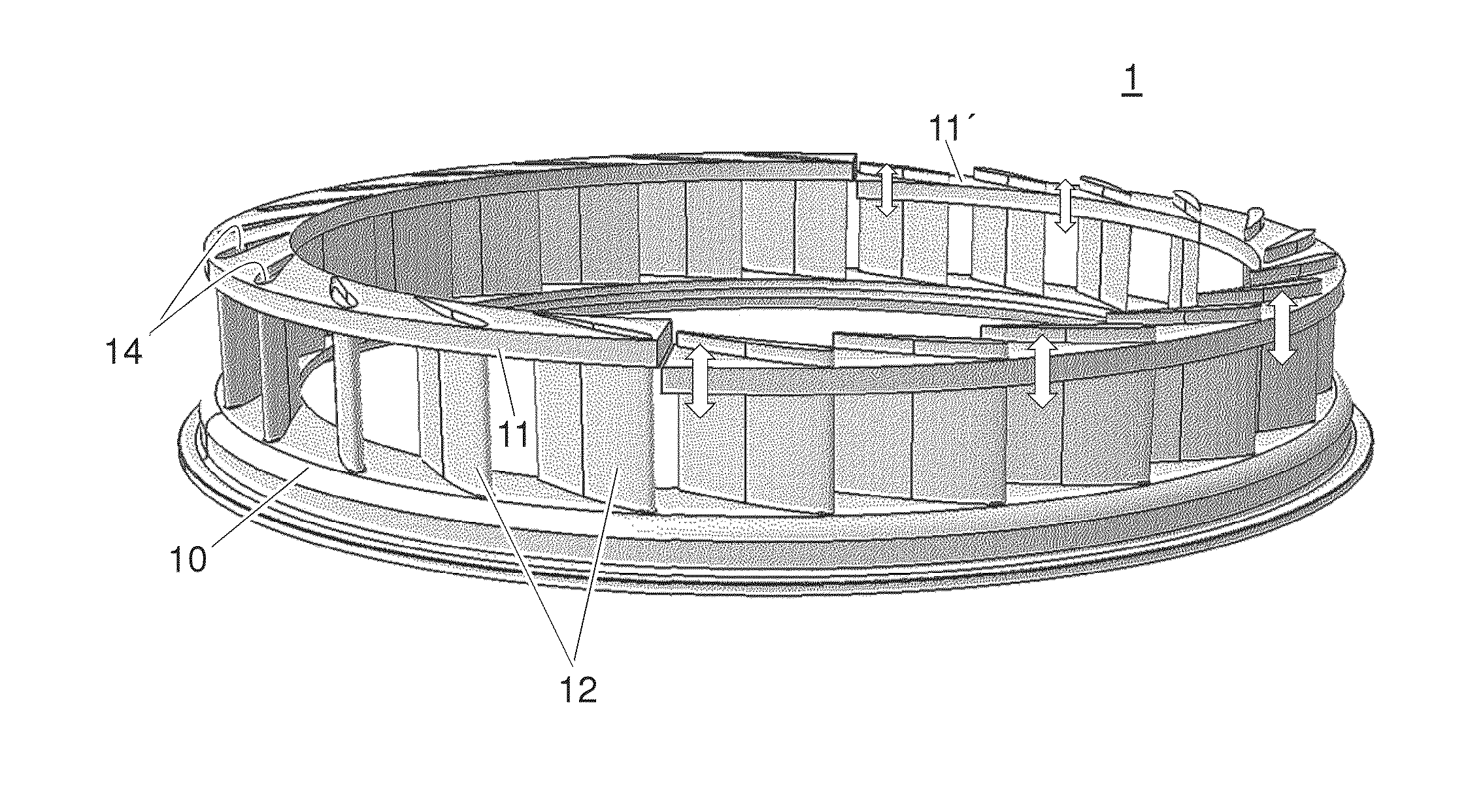
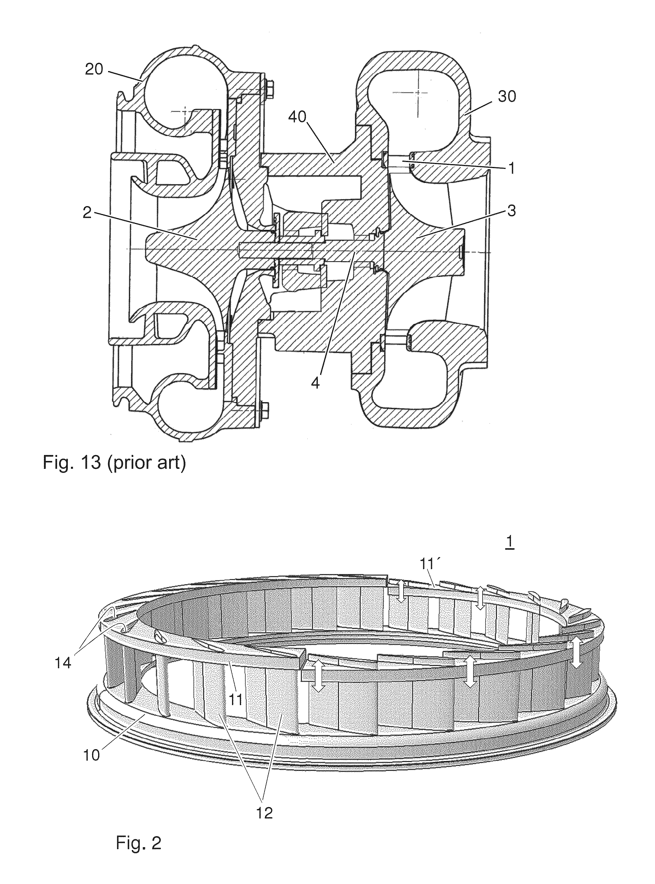
[0027]Exemplary embodiments of the present disclosure create an assembled nozzle ring with the flow guiding of a nozzle ring which is produced in the investment casting process, and which can be assembled from few individual elements in a modular manner for different vane positions and vane lengths.

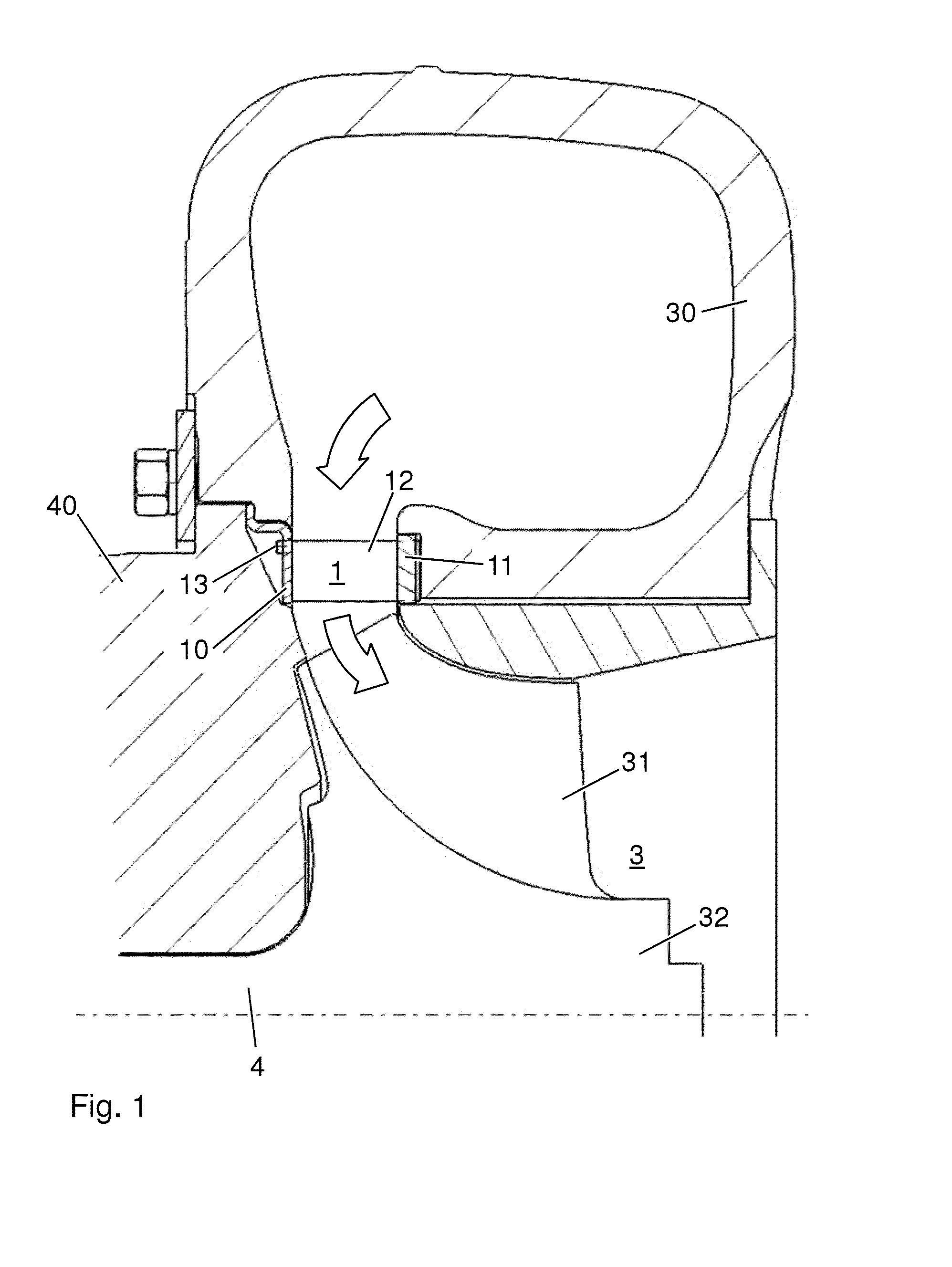
[0028]According to exemplary embodiments of the present disclosure, a nozzle ring can include guide vanes having a pin on one end face which is accommodated in a hole, which is provided for the pin, in a first fastening ring. At the other end, the angular position of the vanes is set in the second fastening ring by means of a corresponding profiled recess in the fastening ring, which corresponds either to the complete surface of the end face or only to the profile of the projections on the end face, and is permanently fixed as a result of the installation of the vanes.

[0029]The pins on the first end face have the advantage that the first fastening ring specifies only simple holes for acco...


PUM

PropertyMeasurementUnit
angleaaaaaaaaaa
angleaaaaaaaaaa
shapeaaaaaaaaaa

Abstract

An exemplary nozzle ring has two fastening rings and a plurality of guide vanes, wherein holes are provided in one of the fastening rings for accommodating pins of the guide vanes, and openings are provided in the other fastening ring for accommodating positioning aids on the guide vanes.

Description

RELATED APPLICATION(S)[0001]This application claims priority under 35 U.S.C. §119 to European application 12193018.4 filed in Europe on Nov. 16, 2012, the content of which is hereby incorporated by reference in its entirety.FIELD[0002]The disclosure relates to the field of turbomachines, such as exhaust gas turbochargers for charged internal combustion engines, and a nozzle ring for such a turbomachine.BACKGROUND INFORMATION[0003]Known turbochargers are used for power augmentation of reciprocating piston engines. So that the turbine can be operated as efficiently as possible, the exhaust gas is deflected in front of the turbine in a row of guide vanes of a guide vane device, also called a nozzle ring. In exhaust gas turbochargers with radial turbines, the nozzle ring includes (e.g., comprises) two fastening rings, which delimit the flow passage on both sides, and a plurality of guide vanes, which, depending upon application, are at a specified angle in relation to the flow and also ...

Claims


Application Information

Patent Timeline
Patent Type & Authority Applications(United States)
IPC IPC(8): F01D25/24
CPCF01D25/246F01D9/042F01D17/165Y10T29/49316F01D9/02F02B37/24
Inventor RICHNER, MATTHIASBATTIG, JOSEF
Owner TURBO SYST SWITZERLAND LTD
Why Eureka
Try Eureka