Wiper control device

a control device and wiper technology, applied in the direction of machine control, vehicle cleaning, instruments, etc., can solve the problems of deteriorating fuel efficiency in the case of electric vehicles, consuming a large amount of electricity of the battery by the wiper motor, and reducing the travel distance in a case, so as to reduce the travel distance and improve fuel efficiency.

Active Publication Date: 2014-05-22
DENSO CORP
View PDF2 Cites 3 Cited by
  • Summary
  • Abstract
  • Description
  • Claims
  • Application Information

AI Technical Summary

Benefits of technology

[0005]In the configuration as described above, even when the voltage of a vehicle battery is lowered in a hybrid car or an electric vehicle, the rotational speed of a wiper motor is controlled to be constant so that the rotational speed of the wiper motor does not drop. Therefore, in a system that controls a wiper motor to maintain a constant rotational speed, a great amount of electricity of the battery is consumed by the wiper motor even if the remaining battery level is low. This may reduce the travel distance in a case of a hybrid car and deteriorate the fuel efficiency in a case of an electric vehicle.
[0006]In a case of an internal combustion engine vehicle, control for maintaining the rotational speed of the wiper motor brings about an advantage that the constant rotational speed of the motor improves the comfort regarding the wiper operation. On the other hand, in a case of an electrically driven vehicle, a constant motor speed can lead to reduction in the travel distance and the fuel efficiency. Under present circumstances, the types of needs for the control system for wiper motors vary in accordance with the type of vehicles.
[0008]Accordingly, it is an objective of the present invention to provide a wiper control device that reduces electricity required for operating wipers.

Problems solved by technology

Therefore, in a system that controls a wiper motor to maintain a constant rotational speed, a great amount of electricity of the battery is consumed by the wiper motor even if the remaining battery level is low.
This may reduce the travel distance in a case of a hybrid car and deteriorate the fuel efficiency in a case of an electric vehicle.
Such a configuration is not effective because the electricity of the vehicle battery can be consumed more than necessary, and wipers that are operated at a high speed by the wiper motor rotating at a high speed can spatter wiped water droplets.

Method used


Image

  • Wiper control device
  • Wiper control device
  • Wiper control device

Examples


first embodiment

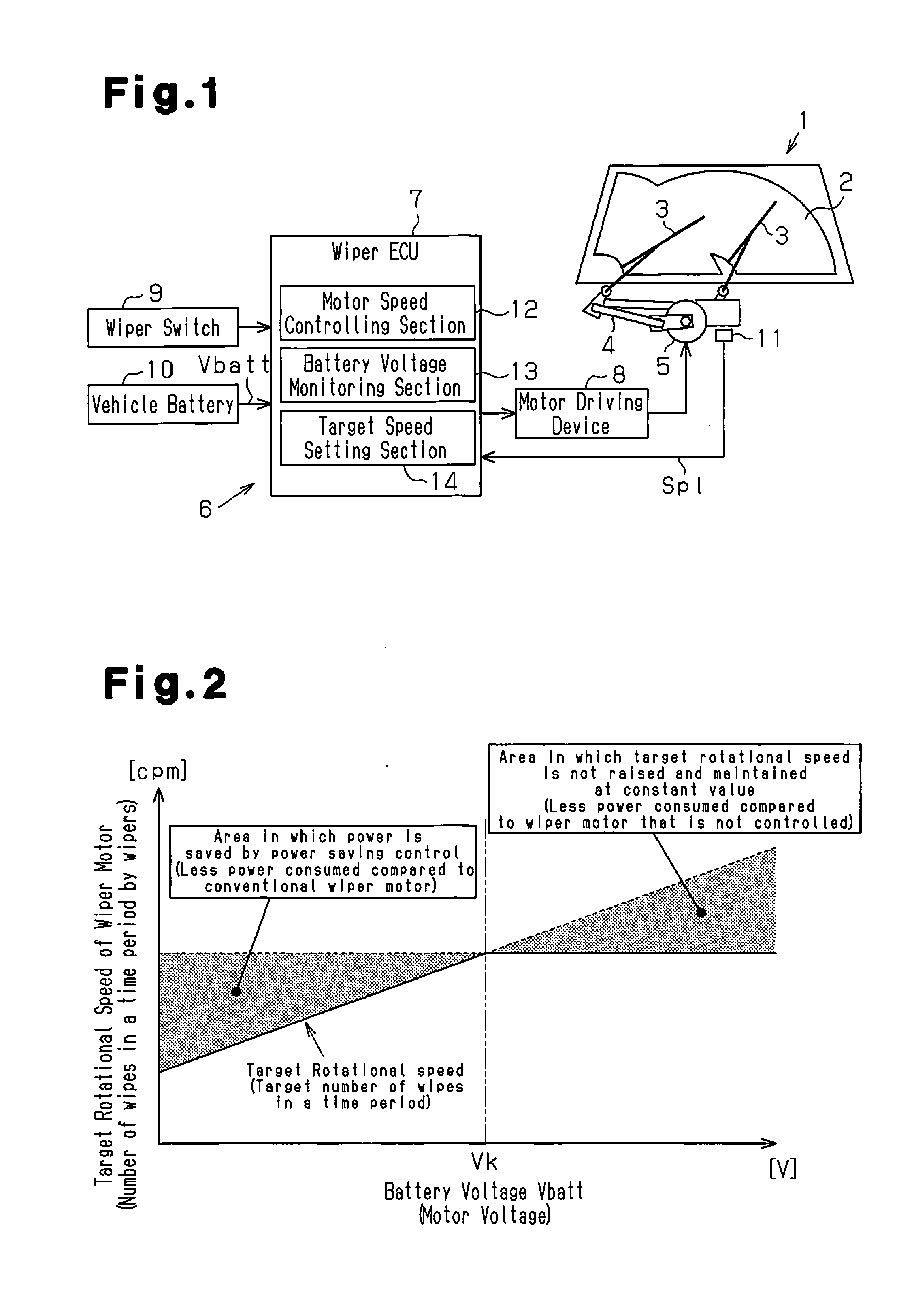
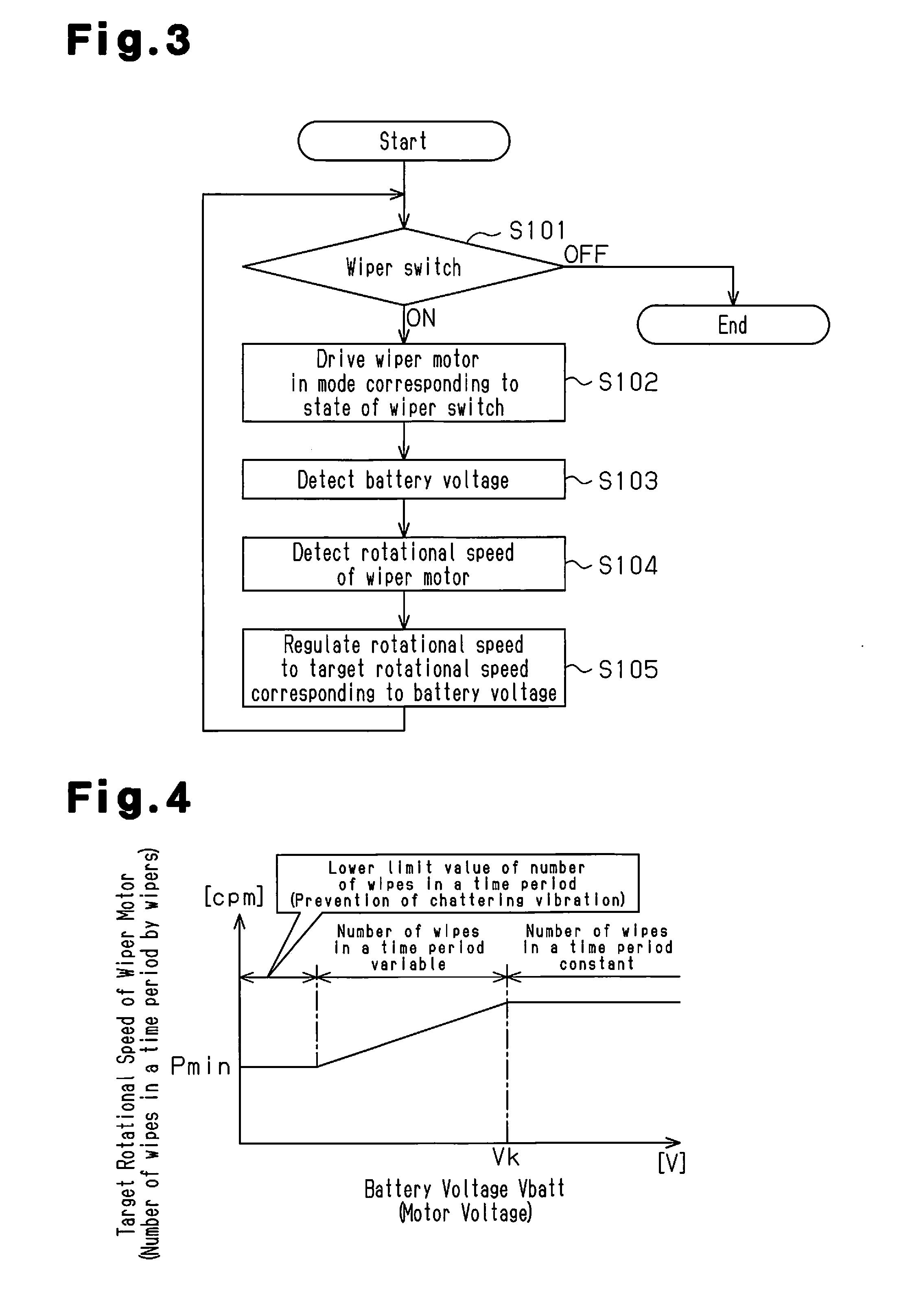
[0019]A wiper control device according to a first embodiment of the present invention will now be described with reference to FIGS. 1 to 4.

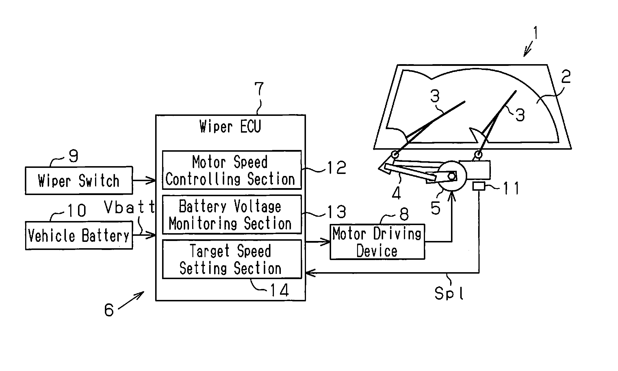
[0020]As shown in FIG. 1, a vehicle 1 includes a window glass 2 and a pair of wipers 3, which wipe water droplets off the window glass 2 through repetitive reversal motions. The wipers 3 are connected to a wiper motor 5, which is, for example, a DC motor, via a conversion mechanism 4. The conversion mechanism 4 converts rotation of the wiper motor 5 into the repetitive reversal motions of the wipers 3. The wiper motor 5 corresponds to a drive section.

[0021]The vehicle 1 further includes a wiper control device 6, which controls operation of the wiper motor 5. The wiper control device 6 includes a wiper electronic control unit (wiper ECU) 7, which controls the wiper control device 6 in an integral manner, and a motor driving device 8, which supplies electricity to the wiper motor 5 based on commands from the wiper ECU 7. The wiper ECU 7 is connecte...

second embodiment

[0043]A wiper control device according to a second embodiment will now be described with reference to FIGS. 5 to 8. The second embodiment is different from the first embodiment in that the wiper control device 6 can be operated in an eco mode, and other basic configurations are the same as the first embodiment. Therefore, the same reference numerals are given to those components that are the same as the corresponding components of the first embodiment, and the differences from the first embodiment will be described below.

[0044]As shown in FIG. 5, the wiper ECU 7 includes an eco mode switching device 20, which functions as a power saving mode switching section. By manipulating the eco mode switching device 20, the operation mode of the wiper control device 6 is switched to an eco mode. In the eco mode, the wiper control device 6 operates the wiper motor 5 in an energy saving manner. One example of the eco mode switching device 20 is a mechanical eco mode switch 21 as shown in FIG. 6A...


PUM


Abstract

A wiper control device controls a drive section for driving a wiper to operate at a target speed, thereby causing the wiper to perform wiping operation. The wiper control device includes a voltage monitoring section, which monitors a power source voltage supplied to the drive section, and a target speed setting section, which sets the target speed. When the power source voltage is lower than or equal to a threshold voltage, the target speed setting section sets the target speed in accordance with the power source voltage. When the power source voltage is higher than the threshold voltage, the target speed setting section sets the target speed at a constant value.

Description

RELATED APPLICATIONS[0001]The present application is a National Phase entry of PCT Application No. PCT / JP2012 / 072149, filed Aug. 31, 2012, which claims priority from Japanese Patent Application No. 2011-202130, filed Sep. 15, 2011, the disclosures of which are hereby incorporated by reference herein in their entirety.FIELD OF THE INVENTION[0002]The present invention relates to a wiper control device that controls operation of wipers.BACKGROUND OF THE INVENTION[0003]As has been known, vehicles are equipped with wipers that wipe water droplets and the like off a window glass through repetitive reversal motions (for example, refer to Patent Document 1). The drive source for wipers is a wiper motor such as a reversing wiper motor. The wipers are operated by the wiper motor to perform reversal motions, while wiping the surface of a window glass. A wiper control device for controlling operation of a wiper motor controls the wiper motor such that the wiper motor rotates at a constant speed...

Claims


Application Information

Patent Timeline
Patent Type & Authority Applications(United States)
IPC IPC(8): B60S1/08
CPCB60S1/08B60S1/0807Y10S318/02B60S1/0896
Inventor NAKANO, HIROYUKI
Owner DENSO CORP
Why Eureka
Try Eureka