Shift register and method of driving the same

a technology of shift register and shift register, which is applied in the field of shift register for flat panel display devices, can solve the problems of low manufacturing cost, inability to secure electrical reliability, and difficulty in large-scale polycrystalline silicon realization

Active Publication Date: 2014-05-29
LG DISPLAY CO LTD
View PDF2 Cites 12 Cited by
  • Summary
  • Abstract
  • Description
  • Claims
  • Application Information

AI Technical Summary

Benefits of technology

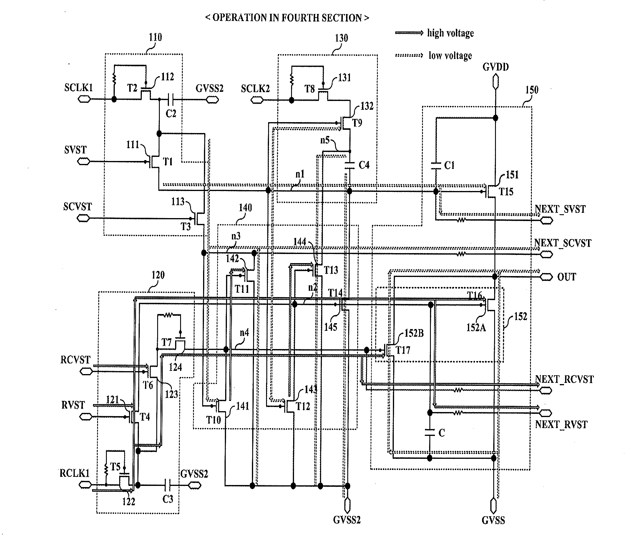
[0021]A shift register includes: a start signal unit configured to control a start of an output signal by using a first start pulse signal, a first clock signal, and a first control pulse signal which are inputted thereto; an end signal unit configured to control an end of the output signal by using a second start pulse signal, a second clock signal, and a second control pulse signal which are inputted thereto; and a plurality of stages configured to increase the output signal to a high-level driving voltage according to a signal supplied from a first node connected to the start signal unit, and decrease the output signal to a low-level driving voltage according to a signal supplied from a second node connected to the end signal unit, each of the plurality of stages generating multi signals for diving a pixel circuit of a display device.

Problems solved by technology

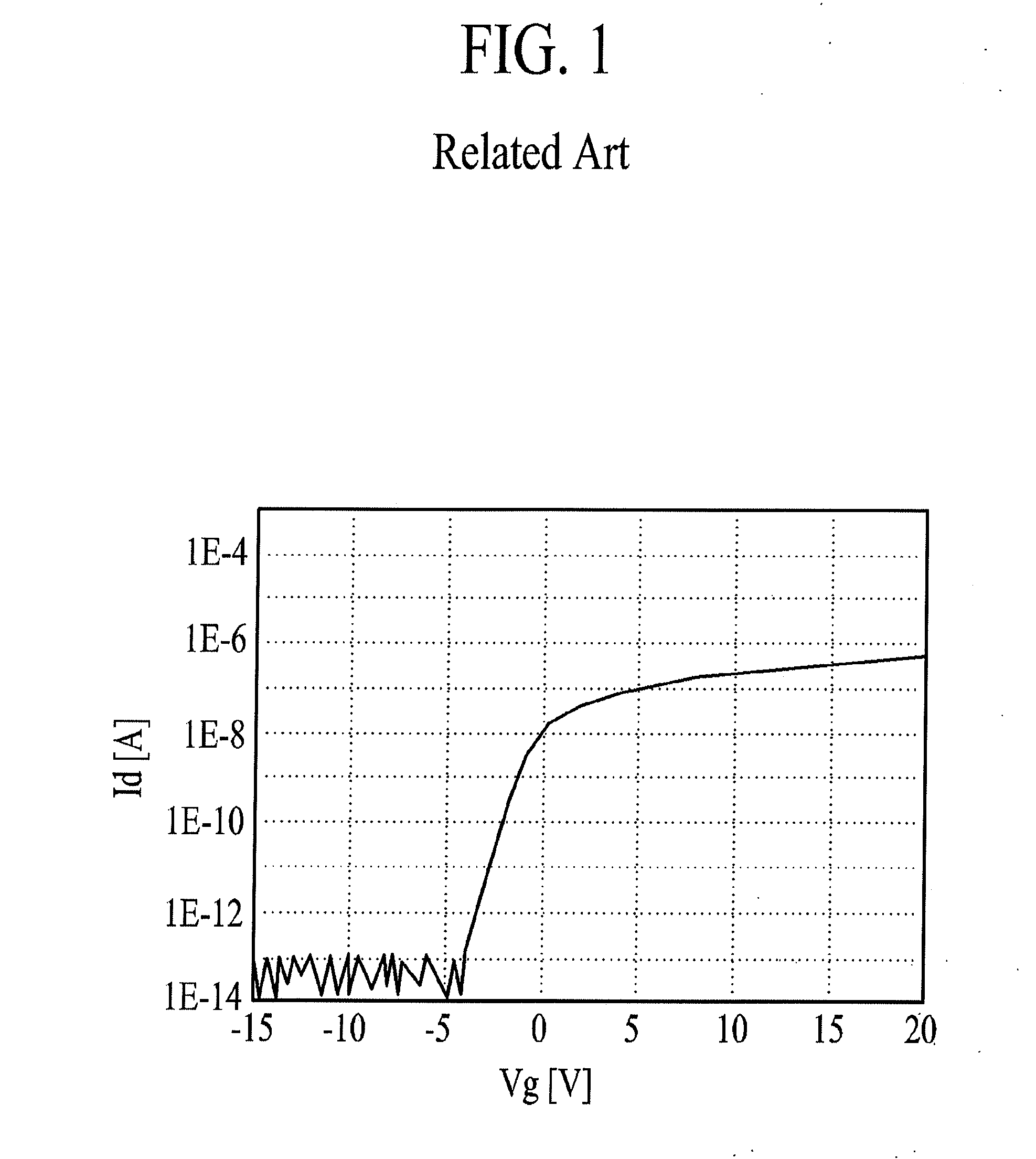
Amorphous silicon is simple in film-forming process and is low in manufacturing cost, but cannot secure an electrical reliability.
Moreover, polycrystalline silicon is very difficult to realize a large area due to a high process temperature, and cannot secure a uniformity based on a crystallization scheme.
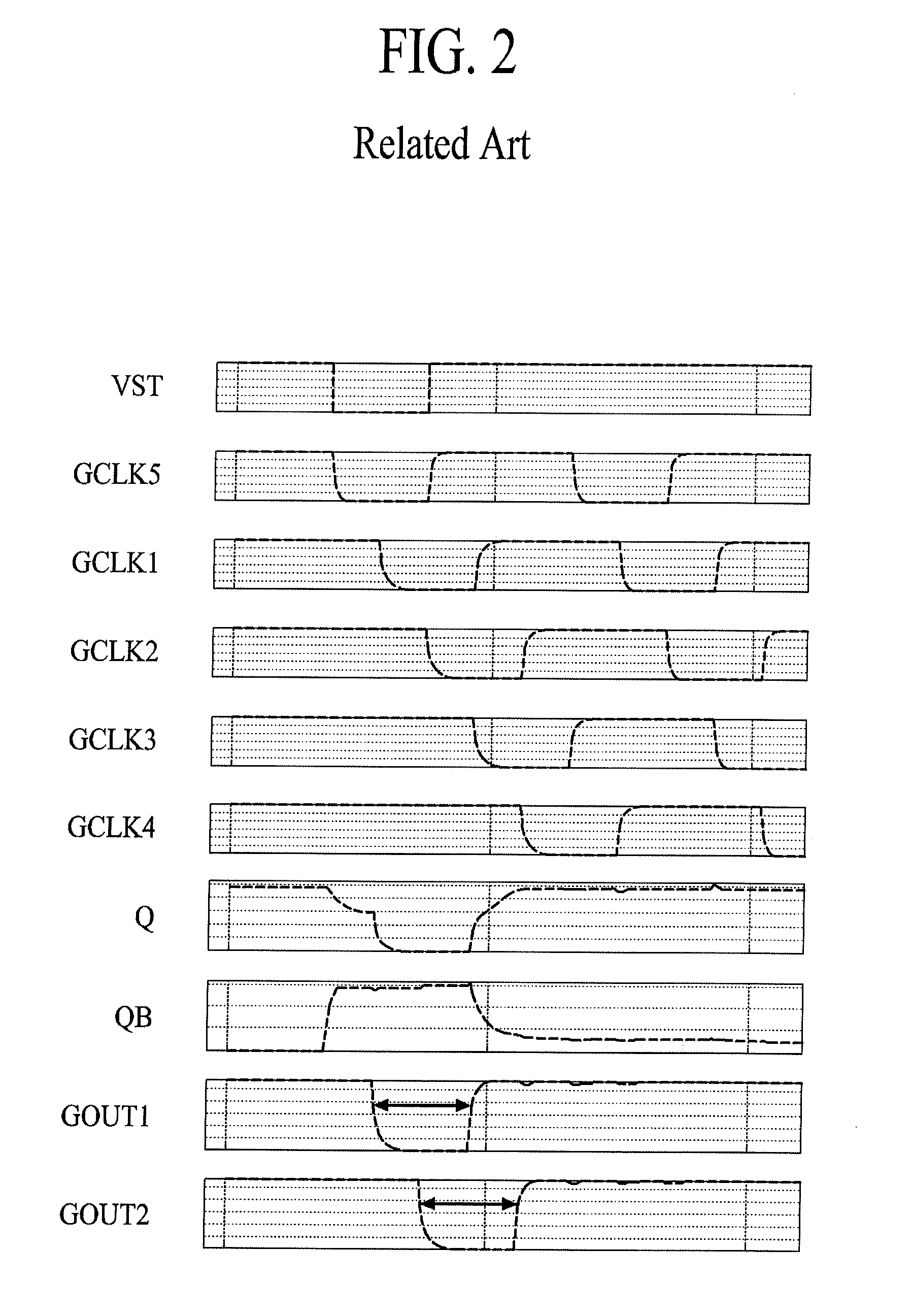
In the GIPT type shift register of the related art, when a layout for driving in one horizontal period (1HT) is set, it is difficult to change a timing of an output signal.
However, the related art shift register cannot generate various output signals, and cannot adjust a timing of the output signals.

Method used


Image

  • Shift register and method of driving the same
  • Shift register and method of driving the same
  • Shift register and method of driving the same

Examples


Embodiment Construction

[0033]In the specification, in adding reference numerals for elements in each drawing, it should be noted that like reference numerals already used to denote like elements in other drawings are used for elements wherever possible.

[0034]The terms described in the specification should be understood as follows. As used herein, the singular forms “a”, “an” and “the” are intended to include the plural forms as well, unless the context clearly indicates otherwise. The terms “first” and “second” are for differentiating one element from the other element, and these elements should not be limited by these terms.

[0035]It will be further understood that the terms “comprises”, “comprising,”, “has”, “having”, “includes” and / or “including”, when used herein, specify the presence of stated features, integers, steps, operations, elements, and / or components, but do not preclude the presence or addition of one or more other features, integers, steps, operations, elements, components, and / or groups th...


PUM


Abstract

A shift register for flat panel display devices includes a start signal unit configured to control a start of an output signal, an end signal unit configured to control an end of the output signal, and a plurality of stages configured to increase the output signal to a high-level driving voltage according to a signal supplied from a first node connected to the start signal unit, and decrease the output signal to a low-level driving voltage according to a signal supplied from a second node connected to the end signal unit. Each of the plurality of stages generates multi signals for diving a pixel circuit of a display device.

Description

CROSS-REFERENCE TO RELATED APPLICATIONS[0001]This application claims the benefit of priority to Korean Patent Application No. 10-2012-0134931 filed on Nov. 27, 2012, which is hereby incorporated by reference as if fully set forth herein.BACKGROUND[0002]1. Field of the Disclosure[0003]The present disclosure relates to a display device, and particularly, to a shift register for flat panel display devices and a method of driving the same.[0004]2. Discussion of the Related Art[0005]With the advance of various portable electronic devices such as mobile terminals and notebook computers, the demand for flat panel display devices applied to the portable electronic devices is increasing. Therefore, flat panel display devices such as liquid crystal display (LCD) devices, plasma display panel (PDP) devices, and organic light emitting diode (OLED) display devices are being commercialized.[0006]A gate driving circuit of the flat panel display devices includes a shift register for sequentially su...

Claims


Application Information

Patent Timeline
Patent Type & Authority Applications(United States)
IPC IPC(8): G09G3/32
CPCG09G3/3291G09G2300/0417G11C19/184G11C19/28G09G3/20G11C19/00
Inventor LEE, HYUN HAENGKIM, HYUN JIN
Owner LG DISPLAY CO LTD
Why Eureka
Try Eureka